• The move to the new server is done. There are some software and database maintenance updates in process. This has us passing the hat around to help out. We appreciate any donations. Seriously, even a dollar helps. The payment page may be found here - https://www.audiokarma.org/support.html

basic folded dipole antenna

mtngun

AK Subscriber
Subscriber
playing around with a mr78 in a fringe area trying different antennas and I am having the best reception, per the signal strength meter and the clearness and stereo separation with a basic folded dipole approximately 24' in length.
I have a question though. When playing around with different antennas I found that this antenna works best with only one of the two leads connected. A lot better. I made this from 22 ga stranded copper per the formula, twisted the leads coming down to the receiver with no balun connected to the 300 ohm terminals. When I have both legs connected reception is good at the lower end of the scale, with one leg it moves up the the center of the fm range.
I'm no expert on antennas, only want to enjoy decent tunes in the shop.
I did research and followed the math and realize I may need to tune the antenna. Before plodding blindly ahead I hope someone can help with answering why my antenna works so much better with only one leg connected.
 
Register to hide this ad
I may have figured it out. seems the receiver has a switch for hi/lo gain switch. going to try it. i was unaware of the switch due to it's location that cannot be seen when in the rack.
 
I have a similar thing going on. I have a DIY quad loop antenna feeding some coax. It works better when I disconnect the shield from one side. The signal meter is actually higher with both sides connected, but the noise floor is lower with only the center conductor connected. I suspect the directionality is affected when both sides are connected and if I were able to aim it - it's strung up in a window sill - I might get different results.
 
another variation

I've experienced much the same thing when experimenting with indoor antennas. As a bit of trivia, the Advent model 400 table radio (which is really a decent piece) came with a single piece of wire 18" long, to be attached to only one of it's terminals. Substituting a "T" dipole did not improve it any. Just something to ponder.
I like like to try ideas for antennas and recently built a variation of the fractal design for FM use. It's a first order variation and rather simple but effective. Appearing to be a dipole, it's reception is quite good and very different in orientation. I tried many configurations before coming to the one I'm using now. It costs almost nothing to make and can provide you with some interesting time spent. Using an analog tuner, I was able to get acceptable reception (mono, that is) from a college station sixty miles away on an adjacent channel to another college station at a right angle to it, only three miles away. The local station typically over modulates to about 130% to make up for it's low power (340W) and the distant one is a kilowatt affair. The antenna does show an improvement over a simple dipole. As time allows, I plan on more work on it. If you might be interested in it, I can supply pix and details.
 
sure, post them up, as a retired engineer that likes to build things a fractal design would be interesting. the station I seek is a 90 watt and I am just outside their coverage area on radio-locator(dot)com
I built a similar antenna for hdtv with a homemade balun and was bringing in all sorts of stations when I was visiting friends in the city. That antenna now graces their window, bonus, they cut the cable not knowing they had superior reception for free. They also have a smaler folded dipole that II made for their radio.
Interesting on the single element connection on the old radio, many new fm portables have but a single extendable whip.
edit--> after posting (10pm) I went out to the shop and played with the gain and achieved only a small increase of signal strength and quality.
 
Last edited:
indoor antenna

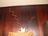
I'll try to post a couple of pix in a day or so. In brief, it's made from 1/8" aluminum wire and a some tidbit hardware. I cut two lengths of wire 35" long and made a form to bend it. The form is 3" long and cut at a 60 degree angle. The angle and 3" dimension is from an experimenters project. he had made one to work the 2 meter band. With no other place to start from, this looked good. The result is a saw tooth looking piece 18" long. (X2) Of all the hype about fractals I've read, one is the wide bandwidth and compact size. Okay, they are used in cellphones and made a huge impact on communications. I only want a compact FM antenna. So, at this point I have a compact dipole. Got that ? I started with an arrangement that was in line, in plane and horizontal. The center is the tap point and I used 300 ohm twin lead. The elements were vertical so as to present their flat side to the signal. Performance was like an average dipole or "T' antenna, to be expected. The smaller size is nice but it's esthetically challenged. In my experiments with it I found it worked better with the elements on edge to the signal. (?) Changing the angle between them made further improvements. Then the big surprise, it works better at the ends ! Not flat side to the direction of transmission but at a right angle. I've made a few more and fixed the angle at a 90 and it looks like any rabbit ear configuration. This seems best for general use. Of course I don't know what I'm doing but it's cheap fun. It has changed my ideas of RF propagation. I've got many more ideas for working with it. The first is to use the center core wire of RG58 (two pieces) instead of 300 ohm twinlead to insure that there is no contribution to signal by the connecting lead in. I don't want to use a balun on the ends and coax because of losses. Multiple elements and stacking are possibilities too. It may become a good attic antenna. I might be on to something or just a crackpot (probably the latter) Maybe after I can get some pix of it up, you might want to try it out. I'd love to hear somebody else's take on it.
 
photo of...

Not much to look at but... give it a whirl. Notice the offset between the elements. Even that made a difference. Another of the "virtues" of fractals, we're told is that they self-excite each other. Oh yeah ? Get the two elements too close together and there is a cancellation. I'd like to try a higher order fractal at some point (where they start to show a snowflake pattern) The 60 degree angle is somewhat of a constant in reference material and also the complementary 120 degree angle. This very basic one is only 60's and the three inch spacing. If nothing else, I got a smaller indoor antenna and an improvement over a simple dipole.
 

Attachments

  • DSCF0309.jpg
    DSCF0309.jpg
    132.9 KB · Views: 68
Not much to look at but... give it a whirl. Notice the offset between the elements. Even that made a difference. Another of the "virtues" of fractals, we're told is that they self-excite each other. Oh yeah ? Get the two elements too close together and there is a cancellation. I'd like to try a higher order fractal at some point (where they start to show a snowflake pattern) The 60 degree angle is somewhat of a constant in reference material and also the complementary 120 degree angle. This very basic one is only 60's and the three inch spacing. If nothing else, I got a smaller indoor antenna and an improvement over a simple dipole.

Now THAT is interesting antenna design. I shall try it, sir. Thank you.
 
sinewave, very interesting. While I have seen similar, I like the basic simpleness of your piece. I plan to continue working on reception here and will include your design.
I do not know much about antenna design except for what I have read on-line. I wonder if the elements were not in a flat plane, rather bent in a spiral array, would the results be worth the efort. I also am curious how a lighter gauge wire would effect effectiveness.
 
you inspired me

I gave some thought to a window based antenna and decided to change my test one (pictured above) to something more suited to a window sill. Here's two pix of the refined original and the latest configuration. I went to coax to make sure I wasn't getting too much input from the feed line. I kept the original elements since even in this kind of crude science, it helps to retain some critical parts and make small changes. The center of the coax is attached to the top element and the lower one is pinched against the bared shield. The shield does extend to the top element. The result is actually less directional but somewhat better reception. I did not experiment with element spacing. The tuner I'm using now is not a fine piece but the signal is quieter.
I think this could fit a window sill and be hidden by curtains.
Your question about wire gauge ? I'd use a coat hanger if I didn't have this stuff. I don't think it'd matter. I did bend a pair of elements so that the 60 degree bend was in both a X-X axis and a Y-Y axis. That way the individual sections would only be on plane every fourth one. Pretty dismal results. There is a good deal of information on winding the elements into a coil.... That would not be a fractal, not even one this basic. Also, you would introduce a certain amount of inductance. Then there is coil length and pitch. By this time, it gets really crazy. I did attempt it once, many years ago. I was given a fifty foot roll of copper tubing and made an omni directional antenna for eleven meters. Tuning it was a chore never really accomplished. High SWR made it a bit scary to risk an expensive transmitter on. I built it in an attic and used four sheets of expanded metal for a ground plane. The coil was 24" dia and about three feet high. I used enough tubing to make it 3/4 wavelength. Only got to use it with an external tuning circuit and found it made a better transmitting antenna than receiving.
I'll swap to a better tuner and report back in..
 

Attachments

  • DSCF0310.jpg
    DSCF0310.jpg
    131.5 KB · Views: 32
  • DSCF0311.jpg
    DSCF0311.jpg
    131.4 KB · Views: 34
Back
Top Bottom