• The move to the new server is done. There are some software and database maintenance updates in process. This has us passing the hat around to help out. We appreciate any donations. Seriously, even a dollar helps. The payment page may be found here - https://www.audiokarma.org/support.html

Luxman L-100U Power Supply Issues

SteveP

Active Member
This thread is an offshoot from the L-100U recapping thread started by 'CohibaJoe'

http://www.audiokarma.org/forums/showthread.php?t=553917

He had asked where to measure and what the setting was for VR901 and VR902 on the power supply/protection board. I dug my L-100 out to see if I could provide any assistance. There are also a couple of L-100 restorations on the web that have provided some info:

http://www.sorscha.org/Content/html/Specials/luxman-L100/html/L100-1.html

https://picasaweb.google.com/vbkolsen/LuxmanL100Renovation#

The second site shows setting the VR's to give +/-58V on pins C7-10, which supply the front end of the power amp boards.

However, there appear to be two different configurations of the power supply board and I'm not experienced enough to decipher exactly what is what (expanded more in the next post) and how exactly the VR's should be set.

The L-100 Service Manual has been scanned is shown on this site:

https://picasaweb.google.com/vbkolsen/LuxmanL100ServiceManualAndSchematic

(and is also available on hifiengine, among other sites).

Steve.
 
Last edited:
Register to hide this ad
As I stated above, there are at least two different configurations of the power supply/protection board.

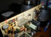
The first picture below is taken from:

http://picasaweb.google.com/vbkolsen/LuxmanL100Renovation#

It shows that C903(4), R905(6), D905(6), and R907(8) are missing from the power supply PCB. That is also the case for the other L100 restoration that I mentioned above. It is also what I find on my amp.

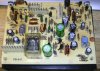
However, as seen in the second picture, CohibaJoe's amp seems to have those parts installed (and follows the schematic in the service manual)
 

Attachments

  • PS1.JPG
    PS1.JPG
    92.2 KB · Views: 116
  • LuxmanL100l.jpg
    LuxmanL100l.jpg
    75.9 KB · Views: 109
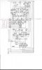
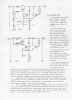
This post shows a blow up of the power supply/protection board schematic, with some of the voltages I measure. I've also included pg.6 of the service manual, which provides, in 'Luxman English,' a description of the function of the power supply, and an image of the board, showing voltages I measure.
 

Attachments

  • Power supply schematic.jpg
    Power supply schematic.jpg
    65.2 KB · Views: 140
  • Luxman L100 Service Manual 6.jpg
    Luxman L100 Service Manual 6.jpg
    90.2 KB · Views: 113
  • Power supply pcb.jpg
    Power supply pcb.jpg
    220.1 KB · Views: 125
  • Power supply schematic trimmed.jpg
    Power supply schematic trimmed.jpg
    83.2 KB · Views: 129
Last edited:
As I see it, CohibaJoe's board looks to follow the schematic (except the fuses seem to have been jumped). My board and the other two seen in the restoration threads are missing the parts noted above. These parts are the ones shown in the dashed box in fig 6.1 of the service manual.

My amp is unrestored and does work. I notice that it does take 12-15 seconds to come out of protection.

The service manual may be written for the L100 and not the L100U (US export version). It indicates 100VAC line voltage and 75V input to the power supply board. I measure +/-87V input to the power supply and I am getting +/- 63V out (vs the +/- 55V indicated in the manual, and the +/- 58V noted in the one restoration). On my amp, varying VR901 changes the +63V reading very little.

The other output voltages from my board are quite close to what is described in the service manual, with the exception of the +/-B2 voltage to the flat amp boards---I get 18.8V and -18.2V, instead of +/-22V. However, I notice that resistors R925 and R926 have been increased from 68 ohms on the schematic to 1K in my amp.

Please pardon the very long winded introduction. It appears that my amp differs in some respects from the schematic. I assume this reflects a change that was introduced, as the two other amps seen in the restoration threads have the same changes.

This still leaves the initial question unanswered: what is the function of VR901(2)? Where should measurements be taken and what should they be set to?

Steve.
 
Last edited:
The description of the power supply on pg6 of the manual indicates that Q901, Q903 and Q905 should all be operative under normal conditions (and with the original schematic).

From the Vbe voltages I measure it looks to me like only Q905 is on. The Vbe across Q901 is 0V when the amp is on. I notice when I turn the amp off the Vbe goes to -.65V for ~5 seconds. Q903 also seems to turn on transiently when the amp is shut off.

I guess this all boils down to:

1) Does removal of those parts make sense?
2) Does it appear my power supply is working properly?
3) How should VR901(2) be set?

Thank you for any insights you can provide.

Steve.
 
I have no experience with this amp but I've seen a lot of differences in Lux amps and whats actually on the schematic. According to the schematic my 507X amp should have some diodes in the PS but I cannot find them on the board.
 
Thank you. Yes, there do seem to be several errors in the service manual and schematic, other than the changes that I noted above.


It seems like two of my links have gone dead overnight. I can't get to them directly either this morning, so hopefully it is just a problem with that server that will get fixed soon.
 
They dont have to be errors, sometimes factories made changes in the original design.
If you are sure yours is all original i would stick with whats on the board. Ive seen a very similar case with a Sansui amp here on AK not too long ago.
 
Oh yes, I agree---I think the missing parts reflect a change that was made during production. The 'errors' I was speaking about are mostly little things--a zener diode in the schematic that is shown with a regular diode symbol, a resistor shown on the schematic that has no value shown, etc.

Steve.
 
I am troubleshooting an L-100U right now...

As far as what the VR901 and VR902 adjust, they are adjusting all of output voltages from the powersupply board (VR901 positive, VR902 negative). No only on the c7-c10 pins (which run to the poweramp boards) but also the voltage supply to the EQ, flat amp, tone, and filter boards. When adjusting the VRs, I'd imagine it would be best to measure the C7-10 pins, and supply even voltages. Assuming the amp is working fine, it should then send same related voltages to other boards

On a side note, the issue I am trying to tackle is my positive output voltages are all okay, but the negative voltage output is only about half as the positive
 
I am troubleshooting an L-100U right now...

As far as what the VR901 and VR902 adjust, they are adjusting all of output voltages from the powersupply board (VR901 positive, VR902 negative). No only on the c7-c10 pins (which run to the poweramp boards) but also the voltage supply to the EQ, flat amp, tone, and filter boards. When adjusting the VRs, I'd imagine it would be best to measure the C7-10 pins, and supply even voltages. Assuming the amp is working fine, it should then send same related voltages to other boards

On a side note, the issue I am trying to tackle is my positive output voltages are all okay, but the negative voltage output is only about half as the positive
My restoration is complete, I found that +/- 58v on the C7/C10 is the best voltage for the poweramp+preamp boards to get best voltages as called for in manual.
FWIW, my PS board is the 'original' one (the one with more parts that follow the schematic) versus the other version with less parts
 
Back
Top Bottom