• The move to the new server is done. There are some software and database maintenance updates in process. This has us passing the hat around to help out. We appreciate any donations. Seriously, even a dollar helps. The payment page may be found here - https://www.audiokarma.org/support.html

New Old Stereo/TV Stand

Bratwurst7s

In The Frying Pan
Subscriber
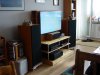
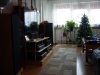
I have a TV/Stereo stand that was largely chosen because it could support my old tube TV, but has the bad habit of stuffing my amps into a small enclosed space and forcing me to stack things. I've been increasingly worried about having the amps stacked that way because of heat and lack of ventilation.

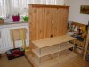
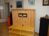
When my son moved out a few years ago he left a TV stand in the cellar and said that I could have it. But it has a couple of problems/limitations. First, the base of the stand isn't deep enough for a full sized amp to sit on and leaves about 4" of the amp hanging out in front. Second, it has 2 glass shelves that are even shallower than the base, and are poorly supported.

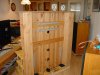
But the back wall of the stand is really nice, and has side pockets that I could use for all of those oversized CD's that won't fit into a normal slot in my CD rack. It's also perfectly sized to mount my new 48" LED TV, and wide enough to allow for 2 amps side by side. So there is potential here.

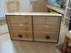
So I decided to mod the stand by building a new base that would be deep enough to fully support my amp, and be wide enough for a second one. I also wanted to provide for some kind of active ventilation for the power amp(s). I would also want to replace the glass shelves with something more substantial, wood, and well supported.

So a few weeks ago I had finally saved enough pennies to head off to the men's toy store and start buying the needed material.

DSC00581.jpg DSC00813.jpg DSC00823.jpg

Cheers,
James
 
Last edited:
Register to hide this ad
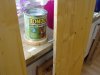
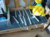
The shelf details are as follows. They are mounted to the back wall with combi lag/machine studs with 8mm threads. Support comes from 8mm threaded rods and 25mm dia alluminum tubing with 1.5mm wall thickness cut to the necessary lengths. Brass acorn nuts and brass washers were chosen to match the warm color of the wood. Finding the right oil for the new portions of the stand proved difficult, especially as the existing parts are now 5 years old and have darkened.

DSC00831.jpg DSC00829.jpg

Cheers,
James
 
Last edited:
With the basic layout completed It was time to address cooling. The base was made with a divider wall down the middle, turning it into 2 chambers. Since the back wall has a large recess in the back I planned to mount the fans hidden back there where they would be hopefully not very loud.

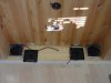
For fans I choose Noctua 120mm NF-P12 PC fans. I've been using their products for a number of years now and like them a lot. The fans have fluid bearings, are quiet, and seem to last a bit longer than forever. They are 12 volt and draw 90mA each. To power them I am using a 12v 1A power supply from an old router that died a while back. Any 12v power supply that give 300mA or so will do. Then I added some filters to complete the air supply.

I initially cut a single 50mm hole centered under where the amp(s) will sit, mainly because that is the largest hole saw that I have and didn't want to use the sabre saw for ascetic reasons. (Like a nice clean round hole.) But that didn't really seem like enough airflow so that's why the circle of 10mm holes surround the center holes. To seal the bottom of the base I cut strips of 4mm self adhesive felt. This also allows me to easily slide the whole stand around on the floor without scratching the floor.

At the moment the power supply is just connected to a terminal block and from there to a y-plug for the fans. I will be adding a switch and poti's in the future to allow for turning on the fans individually and speed regulating them. Or perhaps I'll just pick up a PC fan controller, I suppose that would be simpler. The air supply should be a bit more than the outlet airflow because of the hole sizes, so there should be a bit of overpressure under the base. I'm hoping that that will keep dust out and keep from blowing it up into my amps.

DSC00828.jpg DSC00832.jpg DSC00826.jpg DSC00837.jpg DSC00842.jpg

Cheers,
James
 
Last edited:
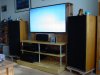
From there it was just a matter of mounting the TV holder and filling the stand with TV and Audio goodness. The big open area behind the backboard allows for decent cable management without a lot of spaghetti. Now I have room for another amp and everything stays nice and cool.

DSC00844.jpg DSC00845.jpg DSC00846.jpg DSC00848.jpg DSC00852.jpg

Cheers,
James
 
Last edited:
Thanks guys! A few things that I forgot to mention.

I bought a set of dowel bore jigs/guides, and the lower platform is held together with hardwood dowels, wood glue and 50mm/2" screws. It's pretty solid. The base platform cover is 120cm wide and 70 cm deep, and all of the platform sides are 7cm high. All the boards are 18mm thick knotty pine.

The 2 shelves are 40cm deep by 120cm wide, and in retrospect it might have been better to buy one 50cm deep shelf and cut it back to 45 cm for the lower one because it's a little bit of a squeeze to fit the Yamaha DSP on it. I deliberately made the shelves not as deep as the base so that they wouldn't completely overhang the power amps for better airflow.

If anyone wants measurements or detail pics of the backboard assy I can get out the tape measure and camera.

Cheers,
James
 
Last edited:
So I finally bought a PC fan controller to use on my rack and got it installed last week. I had some sucesses with it and one notable failure.

The controller is a KazeMaster II 4 fan controller and needs +12v and +5v for power. I already had a 12v 1000mA power supply salvaged from an old router and an old cell phone was nice enough to contribute a 5v 500mA wart. The controller has a nice display and and temp monitoring function, something that I thought might be cool to have.

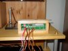
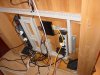
It's enclosure is just some cut up scraps left over from other projects, not real pretty but it won't be seen all that well later anyway. It got a coat of the same oil used on the rack. It got mounted under the upper shelf and at the moment the wires are a bit ugly but I don't want to drill any holes in the back wall till I'm really sure that it will be staying in that spot.

Wires were all marked/labeled (!) for voltage (!) and polarity and secured in a terminal strip. Here is where the notable failure comes in. My recommendation is if you do this then don't do it while you have a really bad headache. Just don't. Because then you might just get stupid like I did and stupidly swap the +12v and +5v wires. The ones that I went out of my way to label and color code.

Because if you do this act of intense dumbness then the display on your new €35 fan controller will get fairly bright for a fairly short time. And then after you correct this mistake the fan controller will still function, but the display will be very dark. Very very dark. Forever. I'm still very pissed off at myself about this, cause I know better and did it anyway.

DSC00912.jpg DSC00913.jpg DSC00947.jpg DSC00949.jpg DSC00951.jpg

So there you have it. Cheers,
James
 
Last edited:
Well, that's impressive! Some great ideas and forethought. Solved a lot of problems and it looks good to boot!

Thanks! For the most part it was a fun project, and except for that last bit of "please kick me I feel like being dumb today" I'm happy with how it turned out. I will eventually replace the fan controller but in the meantime the fan control function still works. Just the display and temp monitor function are dead, but I kinda like the idea of being able to monitor the temp on my amp (someday amps plural). Oh well.

Cheers,
James
 
I've been trying to work out how to make the best use of the temp monitor function of the fan controller (yeah, after I get a new one). There are 4 temp sensor leads, and there is an alarm function that can be set from 55°c to 90°c in 5 ° steps, or off. So I can run a sensor into the top of an amp through the cooling slots.

The question is, providing that the lead is long enough, where in the amp would be optimal? And I couldn't find any max temp specs for my amps so didn't know what threshold to set the alarm to. So today I was checking the caps in a Yamaha A-1020 and saw that they are all rated at 85°c. So I know now that I want an alarm below that. But how far below?

I guess that I'll set it at 70°c at the start and keep an eye on the temps, and try to route the leads near the output transistors. Anyone have any ideas or tips here?

I only have 2 fans installed now but will probably buy 2 more eventually just for grins and giggles. Eventually I hope to have 2 power amps and a pre, as well as keeping the DSP-E800, so I will have cooling options for all 4.

Cheers,
James
 
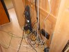
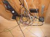
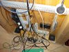
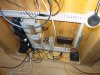
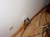
Adding a new dedicated HT amp to my system has taken the cable spaghetti behind the scenes from offensive to obscene. So today I finally got busy and did something about it. I bought some cable channel and got the hidden dark side cleaned up. I left just enough cable slack free of the channels to be able to pull the units forward on the shelves without any binding. Nobody is ever going to see it but I feel strangely better now.

DSC02038.jpg DSC02039.jpg DSC02043.jpg DSC02044.jpg DSC02045.jpg

Cheers,
James
 
So last Thursday I took apart the stand and replaced the middle shelf with one that is deeper.

I had just enough of the same oil that I used originally to oil the stand. Heh. My dumb. I didn't consider the fact that in the last 4 years the original boards & oil have darkened and the new shelf is way too light. I'll have to find some more oil that's a little darker and hit it again.

LOL. Actually drilling and replacing the shelf only took an hour. But removing everything from the rack replacing everything, and re-doing the cable management took 4 hours. I was running out of plugs so I also added a second power strip. The network switch and fan power warts are connected to the 2nd one and all audio/tv components are on the 1st one. Both are going through a bluetooth controlled wall wart so that I can power up the whole thing with 2 clicks of a remote.

I forgot to take a new photo of the back side. I'll try to do that sometime in the near future.

DSC06478.jpg DSC06483.jpg

Cheers,
James
 
OK. So if I put off taking photos of the new stuff I'll just forget so here they are now. This time around I left the signal patch cables and most of the power cords out of the cable channels, it's easier to move components in and out of the rack that way.

DSC06484.jpg DSC06486.jpg

Cheers,
James
 
Back
Top Bottom