• The move to the new server is done. There are some software and database maintenance updates in process. This has us passing the hat around to help out. We appreciate any donations. Seriously, even a dollar helps. The payment page may be found here - https://www.audiokarma.org/support.html

SX-1010 - pop and goes into protection for a moment

w1jim

I can fix it but good...
Subscriber
I've been restoring my new (to me) SX-1010. When I got it the stabilizer board needed refurbing and then I also proceeded to replace all the caps (except the 2 PS caps) and replaced the indicator lights with LEDs (but not the dial or meter bulbs).
Here's the problem; when I engage or disengage the tone control bypass toggle switch or the low pass filter or attenuation (but not the high pass) I get a 'pop' and then it goes into protection for a moment. If the tone is bypassed but I press one of those 2 switches I still hear a 'pop' but it doesn't go into protection (though those functions still operate). Before and then once it resets the rig appears to sound fine. This also occurs regardless of the position of the tape monitor switches so I'm guessing it's something after that, probably in the control amp. I'm thinking I should upgrade the transistors in the control amp but then that's just throwing parts at a problem and isn't the best diagnostic procedure. I adjusted the power amp voltages as per the service manual.
I injected a sinewave through the aux input and looked at the signal through my scope and the waveform 'jumps' when I click one of these switches.

I have another (electrically unrestored) SX-1010 that makes a bit of a 'pop' when I switch the tone bypass but doesn't go into protect so I'm guessing this isn't all that unusual a situation.
Thoughts?
JimB
 
Register to hide this ad
Pops in BOTH channels? Or one?

Either way, one or both channels, you have one or both control amp coupling caps (c47, C48) in backwards, The low filter blocks it.

The older unit has leaky or failed caps allowing DC through.....
 
Check regulator voltages to the control amp (+/-24V) and the four 2.2K dropping resistors (R59~R62). Should have about +/-24V on one side of the resistors, and +/-13V on the other. If this is way off, the coupling caps can be reverse-biased and flowing DC.
 
Glenn is more on track with this. C47 and C48 are installed correctly.
I think this is a high voltage problem.
The control amp is getting +26vdc at pins 3 & 10 and -30 to -32 volts at pins 1 & 12 (should be all 24's).
The voltages at the power supply board (SM voltages in parenthesis):
#14. +65.4 (54)
#15. +26 (24)
#13. +40.7 (35)
#10. -78.3 (-56)
#11. -33.7 (-24)
#9. -18 (-13)
#8. +12.5 (13.4)
#6. +6.7 (6.5)
#1 & 2. 59vac
#3 & 4. 17.2vac​

The power amp PCB is getting +52 and -52 volts.

I suspect that the WZ-320 zener diode(s) are bad.
At the cathode of D8 I'm getting +33.8 vdc.
At the anode of D9 I'm getting -37 vdc.
At the cathode of D10 (WZ-140) I'm getting 13.5 vdc.​

I think the next step is to replace D9.
Thanks big-time for your assistance-
JimB
 
I've been restoring my new (to me) SX-1010. When I got it the stabilizer board needed refurbing and then I also proceeded to replace all the caps (except the 2 PS caps) and replaced the indicator lights with LEDs (but not the dial or meter bulbs).
<snip> I adjusted the power amp voltages as per the service manual.
<snip>

Note to self:
:bash: NEVER :bash:ASSUME :withstpd: AGAIN:bash:that after a recap the other guy re-checked the power supply voltages :bash::bash:
end of self flagellation...

Sorry, the last time I saw those symptoms, that's what it turned out to be, one reversed cap. One thought that was running through my mind was that at 2.2uf, it IS feasible to use non-polarized film caps, it was a mental note to self for in the future.....

Those power supply voltages don't look happy.

here's some useful numbers:
512-1N5246B Fairchild 16 V, 0.5W Zener
512-1N5247B Fairchild 17 V, 0.5W Zener
512-1N5257B Fairchild 33 V, 0.5W zener $0.05 ea
 
Oh, we all do that. My wife is in medicine, every time she comes back from a conference she tells me about the horrible thing I have wrong with me (medically I mean) just because I have a sudden case of the hiccups. We just go for the solution that is most currently on our minds.

The WZ320 is supposed to be a 32 volt zener, will a 33 work? I have some of those in stock. For the 14 volt zener I'm using 2 - 7 volt zeners in series.

Swapping the zener will be today's project unless the weather is nice enough and then I'll replace the upper control arms in my Audi A4 as my Valentines Day present to myself.
JimB
 
Yep, it's clearly the PS. I got the voltage at #11 down to around 24-25 volts and the pop is gone.
Some of the other voltages are still up there so I'll have to attend to them tomorrow, got a gig tonight. And I got my control arms in too!
JimB
 
So after spending too much time staring at the PS PCB and checking passives and solder traces I found a couple of bad transistors. These were likely destroyed when I reinstalled an amp board and where the wires come through the chassis one was touching ground due to misalignment. It really does pay to be careful (duh). There are enough things to go wrong on their own that my assistance in that regard is hardly constructive.
So I'm getting ready to buy some new transistors from B&D Enterprises but found that one of the parts is no longer available and they have a suggested replacement (2SC869 replaced by the 2SC780). If I'm going down that road are there other parts that have upgrades to them that I should consider? Also, are the pinouts going to be the same?
Here's the transistor list for the PS:
2 - 2SA628A
1- 2SC1384
2 - 2SC869 (sugg is 2SC780
2 - 2SD313P
2 - 2SB507P
​

I opened up my other (newer but unrestored) SX-1010 and compared the PS boards. Interesting how in the later units they took some resistors and spaced them from the PCB as well as wrapped them in that braided heat shield material. I guess I'll emulate some of that on this one.
Another mod I'm considering is to relay the output of the display dimmer switch to get the load off of those marginal contacts. That should be an easy one (should be).
JimB

I have different, PROVEN p.s and amp transistor substitutions on the forum. mouser.com parts numbers.

I'll get a under 5(? w/o shipping) buck list together to do the power supply pass transistors and a few resistors. That's how I conquered maddarts power supply problem.

I should have just stressed that from the start.

Q4 2sb507
one 512-KSA940TU_Q pnp to-220 bce 150v 1.5a 25w 4mhz 40-140hfe $0.54

Q1 Q7 2sd313
two 512-KSC2073TU npn to-220 bce 150v 1.5a 25w 4mhz 40-140hfe $0.54 ea

Q8 2sc1384 (ecb)
one 512-KSC2690AYS to-126 ecb 120/a160 1.2a 20w 155mhz 35-320hfe $0.40
or one 512-KSC2682YSTU to-126 ecb 180v .1a 1.2/8w 200mhz 100-320hfe $0.31 (preferred, the current is below 0.1 amp)

Q5 Q6 2sa628 (BCE)
two 512-KSA1013YBU to-92 ecb 160v 1a .9w 50mhz 160-320hfe $0.17 ea

Q2 Q3 2sc869 (bce)
two 512-KSC2383YBU to-92 ecb 160v 1a .9w 50mhz 160-320hfe $0.17 ea

D8 D9 wz-032
two 512-1N5257B Fairchild 33 V, 0.5W zener $0.05 ea

D10 wz-014
one 512-1N5244B Fairchild 14 V, 0.5W Zener $0.05

two ten ohms 1/4 watt metal film 660-MF1/4DC10R0F 0.06 ea
one 3.3 ohms 1/4 watt metal film 660-MF1/4DC3R30F 0.06

was the power supply recapped?
ok, here's the caps:
C7 & C8 470uf (80v) 100v 647-UPW2A471MHD $1.87 ea
C10, C11 100uf (63v) 100v 647-UPW2A101MHD $0.87 ea
C12 & C13 100uf (35v) 63v 647-UPW1J101MPD1TD $0.37 ea
C14 47uf 50v 647-UPW1H470MED $0.25
C18 1000uf (35v) 50v 647-UPW1H102MHD1CV $0.98
C19 220uf (16v) 35v 647-UPW1V221MPD $0.41
C20 & C21 2200uf 10v 647-UPW1A222MHD $0.80 ea

extra parts just in case somebody's looking :
D1 D2 D3 D4 SIB01 100v 1amp
D5 D6 D7 1S1885 100v 1amp
512-1n4004 conventional rectifier 1a 400v $0.06 ea
 
Last edited:
A lot easier to simply replace the lamps with LED's.
Thanks for the advice, I'll just do that then.

And Mark, thanks for the parts list, I'll order that up today along with some "stocking" items.
JimB
 
Continuing with my SX-1010 project, I got my parts order in from Mouser and returned from my latest work trip. Things seem OK with 2/3rds of the AWR-054 PS PCB. It's the "middle" section (as viewed on the schematic) that's wreaking havoc.
Some voltages:
  • #15. 24 VDC (OK)
  • #14. 59 VDC (close, should be 56)
  • #13. 36.5 VDC (close, SB 35)
  • #11. -31.5 VDC (high, SB -24)
  • #10. -71 VDC (high, SB -56)
  • #9. -16.4 VDC (high, SB -13)
  • #8. 13.1 VDC (OK)
So the voltages through the circuitry that uses the 2SB507 and two 2SA628A transistors is too high. (I replaced the 2SA628 transistors -Q5 & Q6- with KSA1013YBU; inserted 180 degrees from the standard positioning to account for the different pin-outs / and / I replaced the 2SB507 -Q4- with the KSC2073TU.)
The voltages at the zeners seems OK:
  • D8. +35 at the cathode
  • D9. -33.6 at the anode
  • D10. +14.1 at the cathode

I've replaced all of the resistors and caps and gone through it several times. I also replaced D1-4 though that was out of bored frustration. All I can imagine is that I either have the small transistors (Q5 & Q6) in wrong or the replacement parts have slightly different parameters.
The unit plays, but clearly I don't want to leave it with these high voltages.
Thanks,
JimB
 
That 2sa628 lead pinout may be wrong, while the board layout would be correct because it would be working on production models.

Q4 is hard to put in wrong, but you'll have to trace which pads are connected to which other components. I suspect the silk screen on the board will be correct, use that as a guide - there's no picture or drawing of that side for me to verify it's correctness.


This thread uncovered the errors in the manual:
http://www.audiokarma.org/forums/showthread.php?p=2419327&highlight=2sa628#post2419327

If the correct orientations on the (tested DMM diode test good) transistors doesn't correct the situation, then:

Please post the three voltages for each of the three transistors: Q4, Q5 & Q6. No cheating, read them AT the transistor leads.

Also do the dmm diode tests on the three transistors that came out.

Also look for hairline fractures in the traces concerned with this regulator section.
 
OK, I'm getting there. I stupidly put the wrong part into Q4. I put one of the Q1/Q7s in there :eek:. When I ordered the parts from your parts list I had Mouser put the replacement part numbers on the bags and mixed them up. Never could get the hang of copy / paste.

Now some of the other voltages on the PS PCB are a little off. I've had some major success tonight so it's time to give it a rest before I blow something else up - I can do that tomorrow.

This afternoon I put in the wide-angle white LEDs behind the dial and meters; looks cool.

BTW, the KSA1013YBU (ECB with the flat up) that replaced the 2SA628 went in 180 degrees off the original position. That tells me that the pinout on the 2SA628 is opposite what the SM schematic shows. It should be BCE with the flat up).

I'm psyched to get this one going. I agreed to move the furniture in the bedroom :naughty: to make my wife happy but I really did it to optimize another system.
Sneaky, but you gots to do what you gots to do.
More soon...
JimB
 
Done!

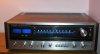
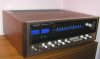
Got the sx-1010 all buttoned up today and playing beautiful music as the new (and improved) bedroom system. Currently I have it connected to some JBL TLX121 2-way bookshelf speakers which are nice enough for now yet clearly budget speakers. Better speakers will find their way home to me in time.
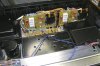
The display dial and meters have all been all re-lamped with some wide dispersion white LEDs. To replace the dial lamps I built a long thin array of about a dozen bulbs with resistors on a piece of perf board. I also mounted 2 1N4003 diodes and a 220mfd cap to keep the flicker from the AC down. The lamps for the meters are comprised of 2 LED aeach with a 220 ohm resistor all in series and then soldered to a blown fuse which all clips into the OEM socket. The function indicators and stereo lamp have also been updated with various color LEDs which just press into place. I like the look and it's especially friendly to my aging eyes.
Everything electrolytic except for the 2 big PS caps have been replaced. I updated the transistors in the control amp as well as the power supply board.
I was lucky to find this SX-1010 in such nice condition; another keeper!

I want to thank Mark aka markthefixer and Glenn aka echowars for their help not just specifically on my unit but all of their other relevant posts that were used for reference.
A donation to the site will be made in their honor and I would encourage others to follow suit when they deem it appropriate.
JimB
 

Attachments

  • sx1.jpg
    sx1.jpg
    50.2 KB · Views: 25
  • sx2.jpg
    sx2.jpg
    55.2 KB · Views: 24
  • sx3.jpg
    sx3.jpg
    126.3 KB · Views: 38
  • sx4.jpg
    sx4.jpg
    89.6 KB · Views: 36
Congratulations!!

I for one would have LOVED to see some pictures of your LEDs.... When you first mentioned it, I thought you had gotten some of whsh93a's led replacements, which have a really nice mellow white.... (blue led with yellow phosphor comes out white)

I had done some individual red & green leds for 4mm bulbs (narrow dispersion angle for sx-3800/3900 buttons) where I had to chuck up the T1 - 3/4 LED in a drill and "machine" off the rim at the bottom to get it to fit - how did the ones you pushed in fit? Was it the rubber grommet mount?

It also turns out that the quote I did that had the transistor arrangements was correct, in fact that questionable one was highlighted in RED...
 
SX-1010 LEDs

The LEDs that I used for the function indicators were standard high brightness T-1¾ ones that I press fitted into the rubber (like) holes that the regular bulbs are inserted into. They actually are a little too narrow beamed; their positioning is a tad bit critical.
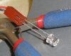
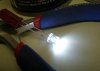
For the main tuning dial I sourced the wide angle LEDs from www.c-leds.com. They were very cheap ($12.95/100 shipped) and they come out of NYC (versus Hong Kong). I used the 5mm size 20,000mcd / 23ma / 3.0-3.2 V parts. They have a fairly extensive selection.
I attached some pictures of the wide angle LEDs.
I guess (actually I know) that I was too scattered brained with work and travel to absorb the nuances of the red part numbers. Likely I just skimmed through it and assumed I knew everything. BTW, when you put one of those transistors in the power supply section wrong they are quite adamant about letting the smoke out.
JimB
 

Attachments

  • Loff.jpg
    Loff.jpg
    22.3 KB · Views: 18
  • Lon1.jpg
    Lon1.jpg
    28.7 KB · Views: 15
Back
Top Bottom