
• The move to the new server is done. There are some software and database maintenance updates in process. This has us passing the hat around to help out. We appreciate any donations. Seriously, even a dollar helps. The payment page may be found here - https://www.audiokarma.org/support.html

How's my layout? 2A3 project taking shape...

Redboy

a few good watts
I got my James Audio output transformers and some other parts in on Friday, and I'm getting ever closer to having everything on hand for my first scratch-built amplifier.

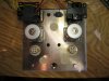
Here's an initial layout idea. Sorry for the crappy pics. I've yet to receive my octal sockets, so there are paper cutouts in their places.

The chassis is a 12" X 12" aluminum plate I got from carpinus7. I was thinking to mount everything through the top and build a simple box to support it. Now I'm thinking maybe I'll put the volume pot through the front side of the box to avoid scalding my knuckles. It gives the tubes a little more breathing room, too.

How's the layout? Does anything need a lot more space? Any glaring errors that jump out at you?
 

Attachments

  • IMG_6111.jpg
    IMG_6111.jpg
    95.2 KB · Views: 80
  • IMG_6113.jpg
    IMG_6113.jpg
    93.9 KB · Views: 52
  • IMG_6116.jpg
    IMG_6116.jpg
    108.1 KB · Views: 84
Register to hide this ad
Looks good redboy, all the AC and PS stuff is at the back/center away from the amp stage and you should have nice short runs from the input to driver tube and output. This is pretty similar to the layout I used for my 45/2A3 and it made for a quiet amp. You could even line up the input jack in front of the output tube to get it even closer to the driver.

I really think you are going to like the James output transformers too, I've heard James iron in 45, 2A3, 50, 300B and 211 SET's and love it. Cool project and I'm looking forward to seeing how this turns out for you.
 
Looks darn good to me, and I like Bill's idea of "snuggling" the RCAs in a little. The other thing I would consider is mounting the power cord connector through the wood base, just so the cord would be flat and out of the way. I read your post in General Audio today about having the guys over for a listen, and between that post and this one, it looks like our audio nirvana trail is running side by side.:thmbsp: I think I can tell you this much for sure though, the moment you fire this amp up, everything changes.:yes: (for the better) Keep us posted, Jay
 
Looks good to me, but know nuthin about building a tube amplifier so Im of no help with layout. You Nate, are going to be the first in the group to tackle such an elaborate tube project I think. Im looking forward to seeing your progress and ultimate success so you can show me how to do it :huge:

RC
 
Hey-Hey!!!,
Just one suggestion, see if you can set the output TX up so that you can rotate it 90-degrees in case it picks up the AC field from the power Iron and humms a bit.

Also, I would face both power irons the same way across the back. There is little risk from interaction between the, but with one 'pointing' towards the output instead of at the other power TX does pose some risk.
cheers,
Douglas
 
looks great

I read that you are making one of JE labs amps? If so I'm doing one as well, the SE 2a3 dx. We can compare notes. I've attached my layout below. I'm finding the big 50uf motor run caps are eating up my room. Plus I'm not sure how much space I need between my 5u4 and one of the caps. I'd hate to have the tube heat the cap up and cause it to burst... Yours is looking really good so far. I'm sure my layout will change a bit, so far I have it set up with all transformers above board, but I'm thinking that my filament and choke can be below deck....
 
Last edited:
It looks very good. I agree about putting the power connector on the back, especially if you're using a premium (thick) power cord. You might try to get a bit more room between the output transformers and the power iron, maybe move the tubes and the output transformers slightly forward, and as was suggested put the volume pot on the front.

I concur about turning the power transformer 90 degrees.

Will you have enough room under-chassis for filter caps and the 2A3 filament transformers? If you put the power connector and fuseholder on the back, you could probably put can-style filter caps topside.

What are the two small round black round items between the output tubes and transformers?
 
Jukin Jay said:
I concur about turning the power transformer 90 degrees.
I'll try that. I think I might need to turn the outputs instead, because of space limitations. Any idea which way the laminations run in the James trannies?
What are the two small round black round items between the output tubes and transformers?
Those are placeholders for where the hum pots will be.

I'll play with this some more today and post more ideas later.

Martin, thanks for the links - looks like some good reading.
 
Take two...

How's this look now?

This moves more things off the chassis. Power switch, fuse assembly, and IEC connector now are on the backside, and the volume pot is on the front.

The choke is now turned the same way as the power tranny. I'm still wondering which way the outputs should be turned. Does the fact that they're potted make a difference?

I put the hum pots on top to show where they'll sit, though of course they'll be mounted under the chassis and only the shafts will protrude.

I plan to use some shielding on the input wires.

Jay, I'm going to use Sprague atoms throughout, and they'll be mounted under the chassis. There should be enough room.
 

Attachments

  • IMG_6119.jpg
    IMG_6119.jpg
    105 KB · Views: 219
I dunno about having the OPT's mounted 'mid-ship', as I think it would be best to have the shortest possible path for your output wire from the Xfrmr to the binding post. What about rotating everything 90 degrees (thus having it wider than long) ?

Regards,
Steve
 
Binding posts will be mounted topside, practically touching the OPTs on the outer edges. I just haven't received them yet, so you can't see them...
 
Douglas would be the guy to ask but I was told the potted James opt was well shielded and orientation wasn't a concern.

I like the new layout, good idea getting the AC stuff on the back and level pot up-front. Putting the binding posts close to opt makes lots of sense to me - input and amp stages up front, output mid amp and AC cord out back on it's own - not commercial rack-amp pretty but sensible from a circuit/input/output perspective.
 
Once I get them oriented in the right direction, how close together can the power and output trannies be? If I turn them, there won't be too much wiggle room. Problem?
 
Redboy said:
Once I get them oriented in the right direction, how close together can the power and output trannies be? If I turn them, there won't be too much wiggle room. Problem?

It looks like the output TX's are symetrical, so that rotating them won't be a problem. Did I miss something in that observation? As to close, look at the Dynaco Mk.III. Its power and output are about 1/4" apart, and they're not potted in round cans either. They are oriented perpendicular to each other in terms of lamination stack and coil axis.
cheers,
Douglas
 
PakProtector said:
It looks like the output TX's are symetrical, so that rotating them won't be a problem. Did I miss something in that observation?
No problem rotating the outputs - they are symmetrical - but I thought you asked me to turn the power trannies...
Turn both of the power Irons 90-degrees. They're pointed right at your outputs.

I'm noob enough to take everything as literally as possible.

Okay to just turn the outputs? We'll get perpendicular either way, right?
 
You can power up the transformer (tape all the other wires!!!) and connect a pair of headphones to the output transformer (primary would be most sensitive) and see how much hum is coupled, and what orientation is best. Something to do while you're waiting for parts!
 
Hey Nate, did you purchase your tubes yet?

I was looking at your last layout and noticed the rectifier. If you can use a 5U4 GB I have 3 in inventory. Yours if you need one.

RC
 
Back
Top Bottom