• The move to the new server is done. There are some software and database maintenance updates in process. This has us passing the hat around to help out. We appreciate any donations. Seriously, even a dollar helps. The payment page may be found here - https://www.audiokarma.org/support.html

Testing 2sk34 fet.

88gibson

Active Member
Paging echowars or someone experienced with testing n channel fets. I'm having problems with an sx-1980 regulator board, and I want to test a 2sk34. How do I test a fet with my multi-meter? I know how to test a transistor. Also does anyone have a better substitute, for the fet is only rated for 50 volts. I found one made by toshiba that is a n channel j fet rated for 100 volts. It has the same case. Any ideas?

Derek
 
Register to hide this ad
Here ya go... (see Word doc attachment)

The FET is a weak point. I tossed them, and replaced them with a home-made current source.

Read here: http://www.diyaudio.com/forums/showthread.php?s=&threadid=92904 I don't get into the current source till post #9.

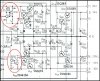
The pic below is the regulator with the mod installed. It eliminates R211, D209, D208, Q206, R214, and the same parts on the negative side.
 

Attachments

  • JFET_Testing.doc
    JFET_Testing.doc
    96 KB · Views: 488
  • Regulator_Mods.jpg
    Regulator_Mods.jpg
    113.1 KB · Views: 1,276
Thanks as always Echowars. I'll keep you informed on my progress. If the j fet doesn't work out I'll build those boards you posted. I had her up to snuff for voltage and then pop! I read your posts from the past and it seems symptomatic of these beasts. I'm actually going to replace the relay driver transistor as well. Any advice on what I should use? I'm hesitant to use another 2sc1438.

Derek
 
Not a critical choice for the relay. Anything with reasonable gain, can handle 60V, and 250mA.

I have a bunch of small boards to make the current sources from. If you decide to go that route, I can fix you up.
 
Thanks Glen! I'm waiting on a transistor order from b and d enterprises. I hope it works out. I would be more than willing to work something out for those boards if the fets don't work out. I changed one of the resistors from a 3.3k unit to a 3k unit per order of the service manual. Have you done this mod? I'm wondering in retrospect ( without having the schematic in front of me) if that was a good idea?

Derek
 
Can't say I'm familiar with that mod.

Dig it up, and fill me in on what it is supposed to do.
 
The technically correct way to check an n-channel FET like yours is to place an ohmmeter across drain and source, with the positive (red) lead of the meter on the drain and the negative (black) lead on the source. This simulates the supply voltage.

Now, short the gate to the source. You should get a reading of a few hundred to a few thousand ohms, depending on the FET and the meter. Less than this, consider the device shorted.

Next, using a bias supply (any variable supply will do) drive the gate negative, relative to the source. At some point, a few volts negative, the gate should pinch off all current flow through the FET, and the ohmmeter should climb to infinity.

If you continue to get current flow, despite a "cutoff" voltage on the gate, you have a leaky device.

This is basically how a transistor tester does a go/no-go test on a FET.

Fred Longworth
 
Back
Top Bottom