• The move to the new server is done. There are some software and database maintenance updates in process. This has us passing the hat around to help out. We appreciate any donations. Seriously, even a dollar helps. The payment page may be found here - https://www.audiokarma.org/support.html

6V6 push-pull DIY amp build - which to choose??

currituckco

Super Member
Hello!

I am building a pair of 6V6 push-pull amplifiers using iron harvested from a Philco console. The original circuit used 2x6V6 (obviously) plus 1x12AX7 and 1x5Y3. I decided not to merely replace caps but instead to build a new circuit.

I have a chassis coming, from fellow AKer ejfud (thank you sir!) which I've decided I want to use to build an SET amp after this one, as I figured out a way to reuse the weird chassis these came on. I'm going to try the Bugle 45 amplifier by Gordon Rankin. But that's for another day, when I find some suitable transformers for that (or bite the bullet and buy the magnequest at $180 each(!))

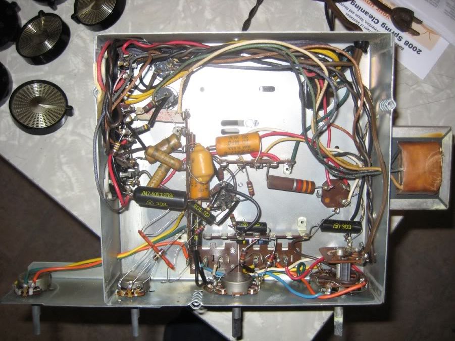
Originally the OPT and octal tubes were mounted on opposite side walls and the PT, multi-can and 12AX7s were mounted on top. This wouldn't really have worked for non-console duty. Tonight I decided to take out my metal hole punch kit from Harbor Freight and make some new holes. I'm only working on one, leaving the other stock in case I get confused about transformer wires or anything else.

Here's the stock one:

IMG_0894.jpg


IMG_0896.jpg


And here's the one I've been working on rearranging tonight. I wish I'd put the rectifier a little farther from the multi-cap, but oh well. Live and learn.

IMG_0897.jpg


IMG_0898.jpg


Anyways, this all was not the reason for my post. The reason for my post is that I'm seeking opinions on what circuit to use.

One that interested me was one that PakProtector posted the schematic for - an RCA circuit using 5Y3, 6AU6 and 12AU7. My concern over trying to copy this is if the power transformer could handle the extra current from the extra tube. I can't find any information on this transformer so I have no idea of its ratings. It is a PHILCO 32-8790-4. I don't imagine there happens to be a way for me to measure the heater current capabilities of a PT...

Here is that schematic:
http://www.freeinfosociety.com/electronics/schemview.php?id=2394

Here is another schematic I found online:
http://webpages.charter.net/dawill/tmoranwms/Elec_Frankenhouse.html

There's also this earlier revision using 12AT7, of which I have some on hand:
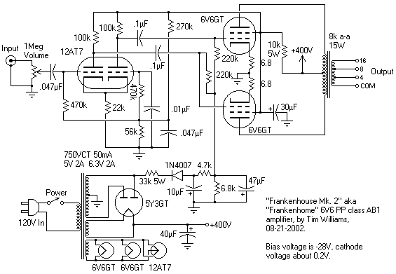
Frankenhome.gif


Or should I use one of those trusty ol' magnavox designs that everyone here seems so fond of? Does anyone have a particular design of those that they like and that they could post or email me the schematic?

One other big question....is there a way for me to tell the proper speaker impedance of the output transformer? These amps do not have normal speaker terminals, being part of a console, and I have no idea what load they expect, and I don't have the speakers that they were originally powering. Anyone have any sage advice?

Thanks!!
 
Register to hide this ad
hey-Hey!!!,
I have a PP 6V6 amp running. It takes a Chicago BO-6 output with a tertiary winding for cathode FB. These are not so common, but aren't awfully 'spensive either. Front end is LTP/diff amp stage with a 6BK7B and a CCS. Headroom for CCS provided by the fixed bias negative rail. This amp is one of my favourites, and I've been planning to have the outputs taken apart so I could try a few mods to them. The schematic looks a lot like curri's 12AT7 drawing.

As to sourcing output Iron, let me share one of my discoveries with you: there are better and less expensive( at the same time) winders than Magnequest out there.
cheers,
Douglas
 
Do you have a Philco model number or chassis number? I might be able to dig up some info.

I doubt an extra tube will bother the transformer - but you can measure the winding resistance to get an idea of capacity. I use a 1A DC power supply and measure the voltage drop (at 1A, 1mV = 1 milliOhm).

The output transformer ratio can be measured at 60 Hz, and impedance ratio is the square of the voltage ratio.
 
Here is the power stage to the GE G7600, a nice little integrated 6V6 amp... Pretty simple output circuit, and it uses an inexpensive driver tube:thmbsp: That RCA circuit will most definitely have better performance, but this is a pretty easy one to learn on and doesn't demand too much from the power supply.
 

Attachments

  • G7600_schem.JPG
    G7600_schem.JPG
    183.5 KB · Views: 404
hey-Hey!!!,
I have a PP 6V6 amp running. It takes a Chicago BO-6 output with a tertiary winding for cathode FB. These are not so common, but aren't awfully 'spensive either. Front end is LTP/diff amp stage with a 6BK7B and a CCS. Headroom for CCS provided by the fixed bias negative rail. This amp is one of my favourites, and I've been planning to have the outputs taken apart so I could try a few mods to them. The schematic looks a lot like curri's 12AT7 drawing.

I didn't quite follow all of this, but I'd love to see a schematic if you have one. I'm not yet at the level that I can design anything, or do much of anything without a schematic.

As to sourcing output Iron, let me share one of my discoveries with you: there are better and less expensive( at the same time) winders than Magnequest out there.
cheers,
Douglas

Good news, certainly. Any specifics? I only looked up the magnequest because that's what the author of the article (and designer of the amp) used.
 
Do you have a Philco model number or chassis number? I might be able to dig up some info.

Stamped on the chassis is 1710 as well as a long number that is different on each chassis, I'm assuming a serial number. That's all I can find.

I doubt an extra tube will bother the transformer - but you can measure the winding resistance to get an idea of capacity. I use a 1A DC power supply and measure the voltage drop (at 1A, 1mV = 1 milliOhm).

I don't quite follow this test - what kind of numbers am I looking to find, and what do I do with them? The only power supply things I have are a 12VDC 2.5A power supply, and a variac fused at 3A, but that doesn't regulate current (right?)...

The output transformer ratio can be measured at 60 Hz, and impedance ratio is the square of the voltage ratio.

Okay - I found further explanation of this here:
----------------
http://www.radioremembered.org/outimp.htm

Checking An Unknown Output Transformer
We can now use this knowledge to determine the impedance of any unknown output transformer. All we need to do is determine the turns ratio of the transformer, and with that information we can calculate what impedance will be reflected back to the primary with a given load on the secondary. The test equipment to do this is quite simple; an ac voltmeter and a variable source of 60 Hz ac is all we need.

To determine the turns ratio we apply an ac voltage to the primary, and measure the voltage in the secondary. The voltage on the secondary will be stepped down by a proportional amount determined by the turns ratio of the transformer. Figure 2 below shows the schematic diagram of the test set-up. A variable auto-transformer (sometimes referred to by the brand name Variac) is used to apply the variable ac to the primary (see note below). An ac voltmeter is connected to the secondary to measure the output voltage. To make the calculation of the turns ratio easy, the input voltage is increased until the voltage on the secondary reads 1 volt. With the secondary reading 1 volt, measure the input voltage to the primary. Since the voltage on the secondary is set to 1 volt, the voltage measured on the primary will be the turns ratio. For example, if the voltage on the primary measures 25 volts, the turns ratio is 25:1 as illustrated in figure 2 below.
---------------------

It goes on to discuss the math once the turns ratio is calculated. I'll try this out later today.
 
Here is the power stage to the GE G7600, a nice little integrated 6V6 amp... Pretty simple output circuit, and it uses an inexpensive driver tube:thmbsp: That RCA circuit will most definitely have better performance, but this is a pretty easy one to learn on and doesn't demand too much from the power supply.

That's an interesting one. If the consensus (which I don't know if it is) is that the RCA design will have the best performace (barring possibly Pak's CCS thing) than I might just have to give it a shot. It's by far the most complicated, and I could easily see myself screwing something up, but if I'm careful and methodical I think I could probably do it.

Just a matter of finding room for the 2 6AU6's...yesterday I was thinking it was one extra tube, but I think it's really two additional 6AU6 tubes that are added with the RCA circuit. I hope these PTs don't melt!
 
Also - is it worth the extra effort to build the RCA circuit using these output transformers? I'm sure these are not exactly 20-20k...will any improvements given by the RCA be nullified by the average output iron?
 
Also - is it worth the extra effort to build the RCA circuit using these output transformers? I'm sure these are not exactly 20-20k...will any improvements given by the RCA be nullified by the average output iron?

hey-Hey!!!,
I find the principle advantage to the RCA circuit lies in its FB path design. It does not take signal from the secondary and feed it back to the input stage. I have yet to find that method yeilding excellent results, OK perhaps, but not the best.

I'd suggest building with your existing OPT's. One can always install better ones later, or put a whole 'nother amp together with better components. The DIY path is taken by me for the joy of building new stuff, not to achieve a goal delivering a single amp. To your exact question, I think it will work very well for you. As implemented, the 6AU6's are a trivial load taking only a small amount of heater power and minimal plate current. Note their huge plate loads...:)
cheers,
Douglas
 
Pak is correct, good iron doesn't necessarily have to cost an arm and a leg! Lots of us other DIY'ers have benefited from Doug's research in this area. Just a small point of mine, maybe not shared by others is, circuit dictates layout and therefore making use of an old laid out chassis can pose some interesting engineering challenges at times!

Terry
 
Thanks Pak! Yeah I did the math on heater current and it comes in under 2A with the 6AU6's added so hopefully I'll be OK. I'd guess that these probably have 2A, right? fingers crossed!

I'm going to build the RCA circuit. I'll keep you all posted as work progresses. Gotta order some resistors, binding posts, and still have to figure out what speaker impedance will be required by these OPTs - maybe i can get to that tonight.

Thanks for all the encouragement!

Simultaneously I might try to put together this project:

http://www.blackdahlia.com/html/tip_44.html

This has kept me dreaming all weekend...I have to go home and see if I have a suitable PT...
 
I found the Sams folder... the output transformer is an odd one. It has a 9K to 4 Ohm secondary...and a feedback tap... and a third tap used as phase inverter to drive the second 6V6 via the cathode. Bizarre! Though I recall seeing this circuit used in some German radios too. I will post it for everyone's perusal and puzzlement.

Sams lists the power transformer as 1.3A on the 6V winding, but that's just the sum of the tubes. I doubt it would have any problem with 2A.
 

Attachments

  • Philco_G1710_amp.gif
    Philco_G1710_amp.gif
    42.1 KB · Views: 232
There's another 6V6 amp that uses a 12AX7 and a 5Y3 rectifier tube on the Interesting KT66 Williamson design thread.

Lar
 
Thanks for the schematic, Tom! That's exactly it! I had noticed the OPT secondary lead going through a 270ohm resistor into the pins 8 of the output tubes and was completely baffled by it. So these transformers are into 4 ohms...hmmm, unfortunately I was hoping to drive my Altecs which are 16ohm. Them's the breaks. Would I need to do anything with the feedback tap when implemented in the RCA design, or just cap it off? I'm also slightly confused by the speaker wiring on the schematic - and what is that second transformer section above the main OPT drawing on the schematic?

Also, comparing the 340-0-340 on the philco schem to the 350-0-350 on the RCA will probably work OK, right? especially with a 120VAC line. I suppose I could adjust power supply resistors if the voltages end up too low.
 
Thanks for the schematic, Tom! That's exactly it! I had noticed the OPT secondary lead going through a 270ohm resistor into the pins 8 of the output tubes and was completely baffled by it. So these transformers are into 4 ohms...hmmm, unfortunately I was hoping to drive my Altecs which are 16ohm. Them's the breaks. Would I need to do anything with the feedback tap when implemented in the RCA design, or just cap it off? I'm also slightly confused by the speaker wiring on the schematic - and what is that second transformer section above the main OPT drawing on the schematic?

Also, comparing the 340-0-340 on the philco schem to the 350-0-350 on the RCA will probably work OK, right? especially with a 120VAC line. I suppose I could adjust power supply resistors if the voltages end up too low.

hey-Hey!!!,
You'd just cap it off and ignore it with the RCA schematic. Having a CT tertiary coil like the Altec 260 did would be an interesting option. That one had 6AU6 drivers too...:)

The RCA schematic runs from a 300V B+, getting that any way convenient will do the job. A pair of 6V6's and associated front end B+ loads will want ~90 mA or so.
cheers,
Douglas
 
Well it's the schematic symbol for an iron core inductor or transformer winding... but it doesn't have a component designation. Is there an inductor? it's not on the parts list either. It (sort of) makes sense to have an inductor there, since it's part of the crossover for the electrostatic tweeter. It would have to be in the multi-henry range to be effective.

Now there are six possible ways to connect that secondary of the output transformer... so there may be a way to match 8 or 16 Ohms. Measure the voltage at each tap with 100V or so across the primary. Or (safer) tape up the primary leads and apply 6.3V across the full secondary (white to yellow) and measure the tap voltages.
 
No inductor - but it may have been connected to the speaker or something (which I don't have). Strange!

I'll put 6.3V across the secondary and measure the tap voltages. Am I measuring them in reference to each other, or in reference to ground?
 
Okay, wait, I *am* confused now.

On on the primary side I have RED BROWN and BLUE, plus YELLOW (which on the schematic is on the secondary side). Then on the secondary side I have WHITE GREEN and BLACK. BLACK I guess is going straight to ground in the schem. OK, so I put 6.3vAC across yellow and white? Is it weird that they are on different sides of the Xformer on the actual unit?
 
One other question - what power rating should the cathode resistors of the 6V6 tubes be? Are 1/2W sufficient, or should they be higher? I have 1W 1.8k on hand for the 6AU6 cathode resistors and am assuming 1/2W is okay for the 12AU7 cathodes? Is there anything else (besides those listed as 2W) that should be higher than a 1/2w rating?
 
Okay, I took some OPT measurements. They were as follows:

All with 100 VAC across the primary (blue-brown), measured in VAC.

Secondary measurements:
BLACK-WHITE: 4.45
BLACK-GREEN: 2.97
BLACK-YELLOW: .212
WHITE-GREEN: 1.51
WHITE-YELLOW: 4.67
GREEN-YELLOW: 3.18

I don't know what to do with these numbers though. Any ideas?

Thanks!
 
Back
Top Bottom