• The move to the new server is done. There are some software and database maintenance updates in process. This has us passing the hat around to help out. We appreciate any donations. Seriously, even a dollar helps. The payment page may be found here - https://www.audiokarma.org/support.html

Harman Kardon trio

Chap

Electrochap
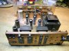
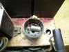
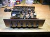
Hi guys, I've just bought a "new" toy and would like your opinions, ideas and a bit more... I paid for this $100. I think it is a fairly good price. The guy that sold it to me said it is in working condition but has a little hum... I didn't try it yet. I opened it and first found one lamp was replaced by a diode and ( I guess) a transistor. Any of you know about it ? pictures following. I also have a few questions about the "parallel / separate" switch inside, the "hum" and "level" adjustment... What are they for ? What do you think about it ? I made a decent deal ? Can you imagine somebody painted in black the chrome cover ? Inside is copper (copper plated or solid ? ).
 

Attachments

  • DSCN2509.jpg
    DSCN2509.jpg
    92.2 KB · Views: 173
  • DSCN2511.jpg
    DSCN2511.jpg
    109.9 KB · Views: 148
  • DSCN2514.jpg
    DSCN2514.jpg
    100.7 KB · Views: 137
  • DSCN2516.jpg
    DSCN2516.jpg
    95.3 KB · Views: 86
  • DSCN2518.jpg
    DSCN2518.jpg
    133.1 KB · Views: 108
Register to hide this ad
Sams Photofact folder 436-7 covers this - I don't have that one though. Also called model A-224. Hum adjustment is to balance out hum from tube heaters - it may not have any effect until you fix the (power supply?) hum.

The rectifier tube should be a 5AR4, I think. Most any brand should be OK here, since it's a relatively low voltage and current.

I wouldn't plug this in until I had fixed the power cord entry and made sure there weren't wires from the broken AC outlet hanging loose inside...
 
Looks quite deathly with those solid state diodes soldered in place of the 5AR4:yikes:, probably not good for the caps too, so a proper rectifier tube should be put in before turning on as well.
 
Two problems with just adding ss rectifiers...

no more 'soft start'; HV slams into everything before the tubes' filaments get the chance to warm up.

higher output voltage (B+) due to higher efficiency of the ss diodes.

EDIT: BTW, those are two mismatched solid state diodes (rectifiers) that I see in the photo of the skt. Is that in fact an octal (8 pin) socket?

It looks like someone soldered the diodes into a socket saver, and just plugged it in to the 5ar4 socket.
 
I have one of these get the manuel form hk websight.It tells you how to set up the hum and buzz pots.They work very well.I did it on mine and it came out dead silent.
 
Obviously I won't fire up the unit until I replace the power cord. And yes, the 2 diodes were soldered on the 8 (?) pin tube socket... I wouldn't do that. Also, I plan to replace all the caps before starting it. There are only 6 I think, not bad except 1 double can and 1 quadruple can too. I've red before there are still some places I can order them from... anybody remember ? I had another "trio" I "refurbished" before and replaced the triple can by 3 stupid little cheap caps.

So you think I should put back the rectifier tube instead of using those diodes ? Is it dangerous to leave them ?
 
The mismatched diodes could also be the source of the P.S. hum because
the filter caps would be getting an asymmetrical wave form which could
leave some ripple.
 
I'm now looking for the right 5AR4 replacing the 2 diodes. Is this tube "full" rectifier ? Because using 2 diodes in my mind only gets half the cycle ? So that amp was working with half it's power ? a lot of ripple ?
 
I'm now looking for the right 5AR4 replacing the 2 diodes. Is this tube "full" rectifier ? Because using 2 diodes in my mind only gets half the cycle ? So that amp was working with half it's power ? a lot of ripple ?

This is a full wave rectified circuit. You are thinking in terms of a transformer that does not have a center tap on the secondary. For that you do need 4 diodes to get full wave rectification. On these old tube amps the transformer typically has a center tap and two leads - you often see them speced out like 360-0-360 meaning there are 3 leads for the high voltage. The center lead is grounded and the each of the other two leads goes to the rectifier tube. The outputs of the 2 diodes are tied together and you get a full wave rectified signal.
 
Nice Trio
But careful...
I wouldnt just pull the diode socket and stab in a GZ34/5AR4
You might just want check under the hood as there may have been other "mods" that you might want to be aware of.
If you post a photo of your engine compartment, we might be able to help
If you need a schematic PM me (too large to post)
WopOnTour
 
Got it !

Finally, found some time to finish work on this one. Replacd all capacitors, rewired some "mods" previously done, Also replaced the tubes with the ones I found in my "Grommes" PG40 ( Telefunken pre amp and "Amperex" O/P ). This last change got me some more watts ( 10 volts RMS in 8 ohms instead of 8 ). And it works.:banana::tresbon::music::thmbsp::smoke: Connected to my 3A Apogee and ....WOW !!! Left me breathless ( almost... ) WHat an amazing sound. Bass is great too; I guess the audio transfos are well designed. I swept it and it is very flat from +/- 35 Hz to 23 Khz. Just found BASS and TREBLE controls doesn't do much...1 or 2 db MAX. Is this normal ? Not that I need them; using the "contour" mode gets exactly what I need. Very very good amp. It really beats my Philips i( 2 watts/channel ). Very happy. ALl I have to do now is to clean it. Trying to get this copper plating shining... WHat should I use ?
 
Two problems with just adding ss rectifiers...

no more 'soft start'; HV slams into everything before the tubes' filaments get the chance to warm up.

higher output voltage (B+) due to higher efficiency of the ss diodes.

EDIT: BTW, those are two mismatched solid state diodes (rectifiers) that I see in the photo of the skt. Is that in fact an octal (8 pin) socket?

You could add a CL-90 current limiter to the primary side of PT, to give it a "soft start". It would also introduce some series resistance to lower the AC voltage.
 
I also own a trio.You cant shine up the copper the blemishes are the underlieing steel showing thru.
One guy doing hk restorations was just painting the board copper.
 
Back
Top Bottom