• The move to the new server is done. There are some software and database maintenance updates in process. This has us passing the hat around to help out. We appreciate any donations. Seriously, even a dollar helps. The payment page may be found here - https://www.audiokarma.org/support.html

I can't believe it still rocked the house(Or my 4400 restoration)

secondslc

mmmmmarantz
**Edit** for more views. I have questions on page 3.

2734969014_51c2386f0b_b.jpg


PHOTO INTENSIVE POST....please have patience...Questions in bold.
Well, as my SR9000G nears completion, i decided to pull the 4400 from my setup to evaluate it.

**aside**I bought the 4400 on ebay on accident since I didn't think my bid for 400 would hold up. I just wanted a unit with a working scope, as thats the only part I know would be IMPOSSIBLE to find. It was my first vintage audio purchase, and I thought since I was getting the king of quads...i would not need anything else. Needless to say, i ate those words. **aside**

The 4400 had two obvious problems, the scope had a curve tracer like display. And every time I would play it, there would be a loud pop, the speaker protection relays would kick in, and reset the unit. The pop would not comeback the rest of the listening session. I lived with both problems by playing low volume till the pop, and dimming the scope to prevent burn in.
2642136911_d35e228972.jpg


With any good restoration, you take lots of before shots, and measure offsets. The dial lamps were not all there, so I have LEDs ready to put in as a final touch.
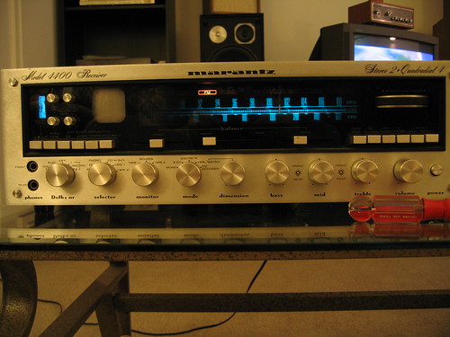
2642136169_bc3889c3f1.jpg

I took offset measurements and was pretty happy with the results. The range was from -.15VDC to .114VDC.
2642974008_6692b7a14c.jpg


Then I started to do a visual inspection of the unit. This thing was messed with before! There were many hold down screws missing...where can I find scews for this unit??
2642976818_505722a4b8.jpg


Then as I hovered over the machine...OH CRAP WHATS THAT.....
2642981562_35865c5f5c.jpg

Yeah, the pictures I took in December show the same hole in the cap. Before I do ANYTHING else to this unit, these caps need to be replaced. Does anybody have a suggestion as to the cap brand/model number that is the easiest drop in? I may just go with the best one I can find on digikey, should I keep the same values or go any bigger?

I remember reading about the scope board having bad fets. How do I test a FET, or should I just go ahead and replace them? And oh look...the wire that goes to j922 is disconnected, could that be the whole problem? What is the easiest way to pull this board as its still connected to the power supply, should I go ahead and de-solder the connections, or does snipping zip ties underneath allow me enough slack to flip the board and solder?
2642985664_dac2b9b6b6.jpg


I was intimidated by this unit for the longest time. But I am confident that I can handle repairing a working 4400 vs a crispy mess.

Any and all advice will be greatly appreciated!
 
Last edited:
Register to hide this ad
Re-attach the broken wire....

If you pull scope board, don't desolder the connections you should be able flip it over far enough.


2$ the wire is your scope issue.


The missing screw may be your pop...as that is part of the grounding system for the power supply. Little metric screws....not that easy to find.

jk
 
Should use the same value caps? Im getting ready to order them.

You must get the same capacitance (the ___ uF), but you can get increased voltage. In fact, it's usually recommended to get slightly increased voltage. I don't know any brands for certain, although Nichicon Muse, Elna Cerafine, and Blackgate are frequently mentioned. It may take a bit of searching to find caps that large, though.

Oh, and while you're in there, clean it up a bit. It looks quite dusty. :yes:
 
You must get the same capacitance (the ___ uF), but you can get increased voltage. In fact, it's usually recommended to get slightly increased voltage. I don't know any brands for certain, although Nichicon Muse, Elna Cerafine, and Blackgate are frequently mentioned. It may take a bit of searching to find caps that large, though.

Oh, and while you're in there, clean it up a bit. It looks quite dusty. :yes:


I used cerafines for my last restore and LOVED them:
http://www.audiokarma.org/forums/showthread.php?t=155960

I just need something to hold me over for now as my source for cerafines takes months to come in :(

I usually try to keep values the same, but have heard some receivers, such as earlier 2270s benefit from increased capacitance. Since I have an early (green scope) 4400, I was hoping the later ones had upgraded caps.

And yes, I'll wash this thing like i did to my 2215.
:music:
 
Hey secondslc:

I have had 18 4400's to repair or re-design, restore.

I know why your main caps are blown up, and they will blow up again if you put new ones in. You NEED to solder you two main dubble diodes on the heat sing SOLID!!
due to extreme high AMPS being pulled from the transformer to main poweramps, these sockets where the high power diodes are mounted on will cause shift in AMPS and in voltage (dc shift). Causing your main capacitors to ''feel unwell'' :scratch2:

I would recommend buying 100VDC 22.000µF.

If there is damage, and i think there is. replace all transistors and caps in main power supply board.... do this first!!! ofcourse with the new 22000 caps.

ooh and another tip :scratch2:
replace the 2sC458 x2 per mono amplifier! on your main amplifiers. they are located just beneath the heatsink under the drivers!!! these models ara defective. replace with 2sc2240.
 
Hey secondslc:

I have had 18 4400's to repair or re-design, restore.

I know why your main caps are blown up, and they will blow up again if you put new ones in. You NEED to solder you two main dubble diodes on the heat sing SOLID!!

what diodes on what heat sink? Just to get clarification..
 
Re-attach the broken wire....

If you pull scope board, don't desolder the connections you should be able flip it over far enough.


2$ the wire is your scope issue.


The missing screw may be your pop...as that is part of the grounding system for the power supply. Little metric screws....not that easy to find.

jk

I agree on your comment + the bad main filter caps.
Re-adjust dc offset to zero and set bias at approx 15 mV and your done.

If i had the thing i would re-cap it all the way.:smoke:
 
I agree on your comment + the bad main filter caps.
Re-adjust dc offset to zero and set bias at approx 15 mV and your done.

If i had the thing i would re-cap it all the way.:smoke:

Once I get my SR9000G (hopefully tonight) working without fires, I will go ahead and put that in as my main listening rig. The 4400 will get all the attention. As many elna cerafines I can get my hands on, the upgrades HAL9000 and jstang talk about, LEDS, full cleaning, and wood case.

The first step is to diagnose everything and get it fully working. Then I will do all the upgrades. Two new caps, diodes and a video transistor should solve that.
 
Digging In

My SR9000G is waiting for a resistor to come in before completion, but otherwise its done.

Now for the 4400. I ordered all the caps for the amp boards and power supply board. I also ordered fets for the scope board, upgraded transistors for the power supply, and replacements for the defective transistors in the amp boards as per HAL9000's suggestion.

But.....

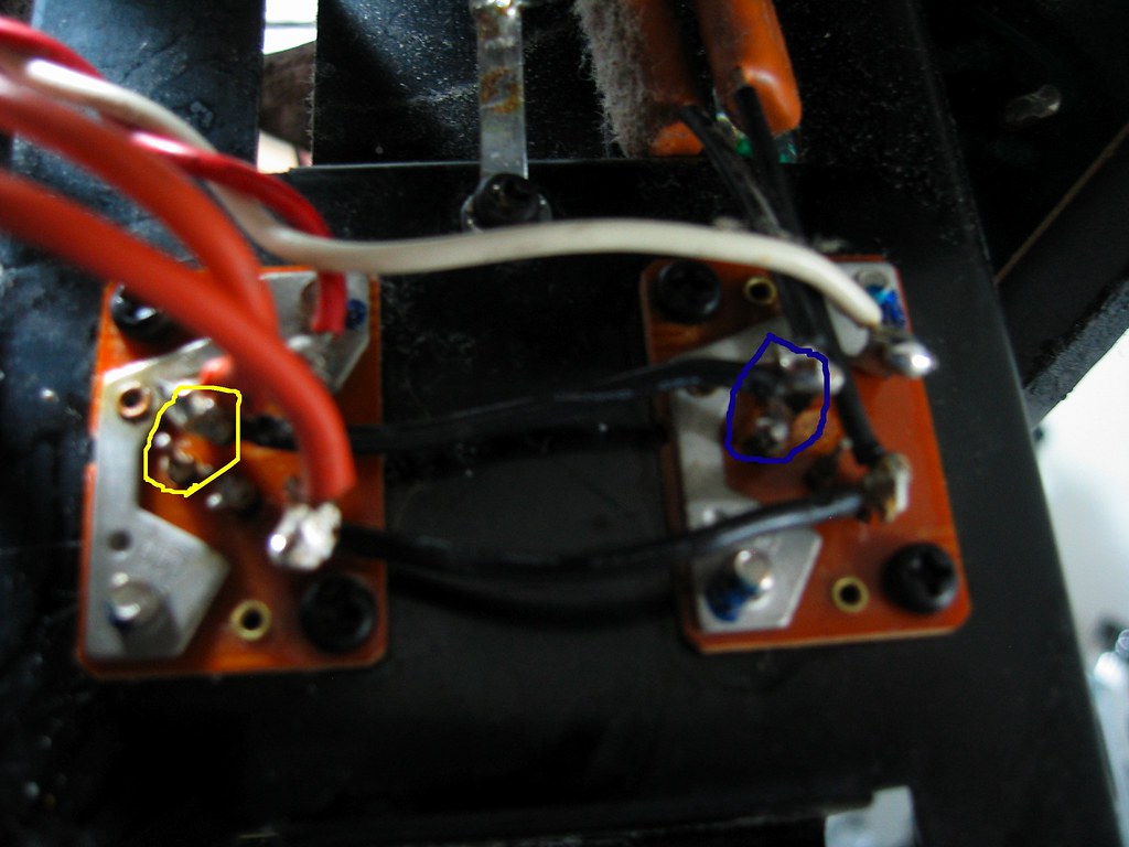
I have a question about the main power diodes I was supposed to check. There was in fact a sleeve that slipped off its pin. I placed it back and soldered it. It seems the diode board on the right has a different configuration, unless there is a bridge missing. Basically, is the connection circled in blue supposed to be there in the part thats circled in yellow. The pins in blue are connected, the pins in yellow are not.....anything wrong with that??

2716207656_57d41fbdf1_b.jpg

2715394699_0511a9ef0a_b.jpg
 
I really can't tell from the photo....Why not just replace the sockets to be sure....


jk
 
I still wouldnt know if the connection is proper.

Basically, the pins circled in blue are connected, the ones in yellow are not. Should the two pins connected in yellow be connected to each other.
 
Work is underway, of course I have questions

I replaced all the caps in the power board and amp boards except for the ones I forgot to order :rolleyes: On one board however, i noticed that a transistor had been replaced, and its heatsink/spacer was missing. The originals are 2sc627, the replacement is a NTE154.
1) Do I replace this one, or replace them all with something better (suggestions???)

2)What is the white spacer underneath there for? It is missing on the replacement, but the other ones have it. Where can I get it?

3)I still don't know what to do with the diodes in my above post, anybody have ideas or need a better explanation of the question?

Transistor in question.
2721260381_1524b6277d_b.jpg

2721260671_1d9d47da3c_b.jpg


Pictures
All pots, switches, connectors, grounds and contacts will be treated with deoxit...front AND back
2721262765_d6986a6292_b.jpg


Power supply caps were all destroyed, again...i really dont know how this thing still worked, and cant wait to hear it once its fixed
2721278863_b8638b34c6_b.jpg


forgot to order an axial cap for the p/s board....oops
2722103496_d3488b5a6e_b.jpg
 
I got your PM, but I'll answer here...if you're measuring the proper voltage on the 20,000µf caps, then the diodes are wired properly (but yes, it looks a little sloppy on your unit). If the diodes were NOT wired correctly, sparks and blown fuses would rule the day.
 
Those old cap's look really good!! ;-)

On the PS board FC or FM?
That's good but never use those on the pre-amp or driver board!

Imo you made a good choice!
 
I got your PM, but I'll answer here...if you're measuring the proper voltage on the 20,000µf caps, then the diodes are wired properly (but yes, it looks a little sloppy on your unit). If the diodes were NOT wired correctly, sparks and blown fuses would rule the day.

crap....thats the issue. I know the unit was working before, but I don't know if i broke the connection on the diode while taking it apart. So basically I need to test the voltage, but to test the voltage it needs to be plugged in. But when its plugged in and wired wrong, lots of bad things will happen.....:tears:

I used FC wherever I could, are they poor quality for the amp boards? I always hear good things about them... I will happily replace them on the amp boards since there are only 4.

I used FC on my SR9000G, could that be whats causing my issues?? :(
 
You have a schematic?

Even though the 4400 looks like a real beast... Its modular/plug in cards make it some what easy to trouble shoot....

Start by disconnecting the power supply board totally on its input and output sides. ....Also remove the two Power amp boards. If the main fuse is still blowing, the issue is with the Diodes or the main supply caps...or a shorted wire on the output of the transformer....


If the Main fuse does not blow.... Re-install the power supply and connect the input only and test.... then the output and test.... then one amp board at a time....


johnk
 
You have a schematic?

Even though the 4400 looks like a real beast... Its modular/plug in cards make it some what easy to trouble shoot....

Start by disconnecting the power supply board totally on its input and output sides. ....Also remove the two Power amp boards. If the main fuse is still blowing, the issue is with the Diodes or the main supply caps...or a shorted wire on the output of the transformer....


johnk

I have the SM but cant find where the diodes are mentioned other than being part H009 and H008. The unit never blew fuses, im just afraid it will if these diodes are now connected wrong. Ill pull the main boards and see what happens when I plug it back in. If no kaboom, ill install all the cards.

This thing isnt a beast to work on since the cards do come out, but its just friggin heavy, and crammed with SO many things to clean
 
Well you want and you can wait ... I can snap picture later tonight of my parts 4400 and post it....


johnk


I have the SM but cant find where the diodes are mentioned other than being part H009 and H008. The unit never blew fuses, im just afraid it will if these diodes are now connected wrong. Ill pull the main boards and see what happens when I plug it back in. If no kaboom, ill install all the cards.

This thing isnt a beast to work on since the cards do come out, but its just friggin heavy, and crammed with SO many things to clean
 
Back
Top Bottom