• The move to the new server is done. There are some software and database maintenance updates in process. This has us passing the hat around to help out. We appreciate any donations. Seriously, even a dollar helps. The payment page may be found here - https://www.audiokarma.org/support.html

Recapping the Tannoy Monitor Gold LSU/HF/12/8

Redboy

a few good watts
I pulled my speakers out of the system the other day to put some finish on the cabinets, so I figured it's as good a time as any to do some crossover work.

Tannoy Dual Concentrics are essentially a two way speaker built into a single frame, and they've got an interesting crossover network. The crossover itself is built into a nice plastic (or metal, depending on the model) box, but there are also some tone control switches mounted on an attached tether. The idea is that you mount the crossover box inside your speaker cabinet, and the switch plate mounts through the back.

Some pictures at this point will help.

Here's the switch plate:

IMGP9251[1].jpg

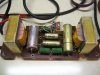
And here's how it all goes together. The crossover box is the narrower one on the right:

1213499856.jpg
 
Last edited:
Register to hide this ad
There's pretty good consensus among Tannoy users that the crossovers can benefit from new capacitors and bypassing the switches. This makes sense to me. I've heard firsthand what new caps can do for a speaker, and eliminating the extra run of cable and switch gadgetry in this design could only help.

Of course, you give up your tone controls by bypassing the switches, but I've found that once I settle on my preferred settings, I never change them anyway. After listening for a while, I knew where I wanted them.

A visit to Hans Hilberink's excellent Tannoy Monitor Gold site will give you crossover schematics for this driver.
 
Surgery begins!

The first thing to do is to drill out the rivets that hold the crossover box together. This is a little unnerving, but pretty simple work.

Inside, your first view is of the backside of the circuitboard.

Remove a couple of tiny screws, and the whole thing pops out. Here it is in it's original, unmolested state:

IMG_8300.jpg
 
Last edited:
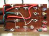
First, let's take a look at the backside of the board. We'll remove the control switch wires coming in from the right hand side of the picture below:

Before:
IMG_8301.jpg


After some judicious snipping:

IMG_8306.jpg
 
Last edited:
Here's where the schematic comes in handy. You need to connect the appropriate points on the board itself to compensate for the absence of the switches. I also mounted some of the new resistors on the backside of the board to make room for the much larger replacement caps topside. That's kind of too bad, because the original resistors measured well. Oh well, I've been happy with the Mills resistors I chose for this project.

Here's how I did mine:

IMG_8320.jpg

IMG_8312.jpg
 
Last edited:
Topside, it's a real trick to squeeze in the new caps. These wouldn't have fit without moving the resistors to the backside of the board. I used Solens for the low pass filters, and Sonicap Gen Is elsewhere:

IMG_8310.jpg


IMG_8311.jpg
 
Last edited:
I've got one down, and the second should not take long. I'm still considering whether to replace the wiring while I'm at it, but I intend to do some listening! :music:
 
Soon, my friend. Soon.

I got the other crossover done tonight. No problems there. I'd take pictures, but it looks just like the first one.

Cabinets have the last coat of finish on them. I ended up doing four coats. Now I'm waiting for the funk to dissipate a bit before I bring them inside.
 
I'm going to drag them in tonight and see if the Danish oil smell has mellowed enough to tolerate. The crossovers are done for now, and I ended up replacing the wiring from terminals to XO box. I'll leave the XO box to driver wiring for now.
 
E x c e l l e n t !

simpsons-montgomery-burns.jpg
 
Back
Top Bottom