• The move to the new server is done. There are some software and database maintenance updates in process. This has us passing the hat around to help out. We appreciate any donations. Seriously, even a dollar helps. The payment page may be found here - https://www.audiokarma.org/support.html

SX-D5000 bias/idle current adjustment

jgmacv

Fluroscan Lover
Please excuse my ignorance in this matter, but I want to make sure I'm doing this adjustment correctly on my SX-D5000. Page 25 of the SM gives the idle current procedure that includes adjustment and measuring points. The measuring points on this model are at the bottom of the board and are difficult to get at. The SX-D7000 has the identical board, but the manual instructs measuring points at the cut-out test area, which is much easier to do. After careful measuring, I've determined that the cut-out of the SX-D5000 are the same as the published measuring points (28, 25, 20 & 17). Also, I'm wanting to verify I'm reading my DMM correctly. The pic shows the DMM measuring test point #20, with a reading of what I believe is -.070mV (SM calls for 120mV) at this point. Finally, why would the D5000s SM call for measuring points much more difficult than the D7000? Again, my inexperience shows, I'm still trying to learn. I did adjust to specified points per the SM. Any guidance is appreciated (I will insulate the probes better--promise).
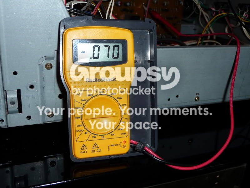
Picture029.jpg


DMM reading

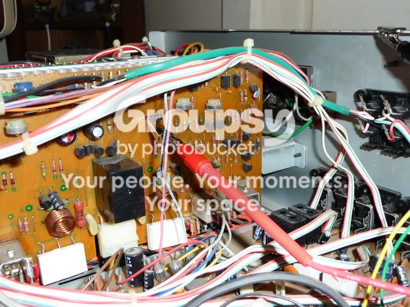
Picture028.jpg


DMM lead at measuring point 20, other lead grounded at chassis

thanks
 
Last edited:
Register to hide this ad
FIRST and foremost, measuring idle current DOES NOT involve connecting to a ground!! WHATEVER you adjusted it to, it won't be correct with a ground based measurement. In fact it could be dangerously (to the transistors) high....

Why in the second picture isn't the second probe connected to the other wire spanning the square hole in the board??

One DMM lead (red) is to be connected to pin 28 (or 17 on the other channel) while the OTHER dmm lead (black) is to be connected to pin 25 (or 20 on the other channel) . THAT'S how...

As to why, it's easier to name a pin rather than reference "the square hole in the board". I suspect that there was a fixture that mated the hole during production, that when pushed in, hit the wires and made it possible to read the value faster. No possibilities of measuring the wrong spot or SHORTING pins with a probe at production speeds. Later they relented and TOLD us about the shortcut (maybe they were afraid of someone doing what you did in the picture - shorting danger is HIGH) , OR a different group of people wrote the other procedure.

As to why the reading you are getting (if it is wrong WITH your corrected measuring procedure) , you need to read the two voltages AT EACH HALF of the dual emitter resistor. The center wire is the output terminal, the two outside connections are the pnp and npn output transistor's emitters, pins 25 & 28 (23) or pins 17 & 20 (22). The output is () but there's a coil/resistor combination as well as the protect relay contacts between that pin and the actual resistor lead where the reading counts..

Sorry about the delay, the last time I was on was the 5th... external matters have monopolized my time, and will do so for the rest of the week.
 
Last edited:
After reading this thread I decided to check the idle current on my SX-D5000 because this unit has always had a good amount of heat buildup coming from the heatsinks. I'm thinking maybe the idle current needs adjustment so I connected my DMM according to markthefixer's instructions and I'm getting readings of less than 3mV on terminals 28 and 25 and also on terminals 17 and 20. The service manual shows the adjusted value to be 120mV on VR3 and VR4 and 150mV on VR5 and VR6. If I'm reading the service manual correctly this unit's readings aren't even close to what they should be. Do I need to adjust each of the four measuring points (VR3-VR6) up to the corresponding mV value (120mV or 150mV)? Could the low mV readings cause this thing to heat up a lot? I would have thought lower readings would be better.
 
After reading this thread I decided to check the idle current on my SX-D5000 because this unit has always had a good amount of heat buildup coming from the heatsinks. I'm thinking maybe the idle current needs adjustment so I connected my DMM according to markthefixer's instructions and I'm getting readings of less than 3mV on terminals 28 and 25 and also on terminals 17 and 20. The service manual shows the adjusted value to be 120mV on VR3 and VR4 and 150mV on VR5 and VR6. If I'm reading the service manual correctly this unit's readings aren't even close to what they should be. Do I need to adjust each of the four measuring points (VR3-VR6) up to the corresponding mV value (120mV or 150mV)? Could the low mV readings cause this thing to heat up a lot? I would have thought lower readings would be better.

My SX-D5000s, SX-D7000 and SX-3900 all generate a good amount of heat, and all are adjusted properly. I think it's just the nature of these NSA units.
 
My SX-D5000s, SX-D7000 and SX-3900 all generate a good amount of heat, and all are adjusted properly. I think it's just the nature of these NSA units.


My recent SX D5000 is slightly warmer then the SX D7000:yes: But not too hot when touched:thmbsp:
 
Thanks for the info guys. When you adjusted yours jgmacv did you adjust the one channel to 120mV and the other to 150mV? According to the service manual I think those should be the correct readings. If that's true, I'm going to have to adjust mine since I left both channels at 2-3mV thinking lower was better.
 
Thanks for the info guys. When you adjusted yours jgmacv did you adjust the one channel to 120mV and the other to 150mV? According to the service manual I think those should be the correct readings. If that's true, I'm going to have to adjust mine since I left both channels at 2-3mV thinking lower was better.

You are reading the procedure wrong...... 2-3 mV is the offset voltage read at the output, 120 and 150 mV is read across t he emitter resistors of the output transistors.

The end target for idle current read as a voltage is 150mV

The 120mV is a VERY IMPORTANT intermediate step!!!!

Not following the procedure exactly WILL destroy the amp in the wrong sequence. Because the second step in the opposite order will suddenly jump the idle current to a horrendously huge number.

There are 4 pots, the first two set the reading to 120, and later reading THAT EXACT SAME POINT adjust the second pot in each amp from 120mV to 150mV.

If you have ANY doubts, read the sx-3800 procedure - I just checked and it is an english version, noyt a table plopped down, plus the pin numbers AND the VRx numbers are the same.

If you have ANY doubts - ASK - it's easier than fixing it....
 
Last edited:
Thanks a lot Mark. I think I understand what you're saying but to be on the safe side please double check this: 1) Connect the red DMM lead to terminal 28 and the black to 25 and adjust VR3 to 120mV. 2) Then connect the red lead to terminal 17 and the black to 20 and adjust VR4 to 120mV. Then repeat steps 1 and 2 but adjust VR5 AND VR6 to 150mV. All four of the pots have to be adjusted in order. Is that correct?
When I first checked terminals 28 and 25 and then terminals 17 and 20 I got a reading on my DMM of 2-3mV. Is it possible that over the years the idle current could have gotten that out of whack?
 
No, that's deliberate.

You'd better test one channel at a time on a dim bulb tester - 100w may not be enough for this, even one channel at a time.

And remember, start out with the pots zero'd as the manual calls for it and you didn't detail in your last post - you DID find and read the sx-3800 procedure? It's the SAME amp.
 
So, you think maybe someone was messing around in there before I had the unit?
I did check out the SX-3800 manual. The procedure is definitely spelled out better than in the SX-D5000 manual. I didn't zero-out the four adjustment points when I checked the idle current the first time so I'll make sure to do that the next time.
Can I go ahead and adjust the the idle current up to 120mV and then 150mV or do I really need a dim bulb tester? I'm not really sure what that is!
 
Gave it another try (no load or input signal - aux function selected) with the four adjusting points turned counter-clockwise and the readings (when DMM connected to terminals 28/25 and 17/20) are still around 2mV on both channels. Carefully turning VR3(when DMM connected to terminals 28 and 25) and VR4 (when DMM connected to terminals 17 and 20) didn't change the readings at all. They stayed at 2mV. Also, the heatsinks are generating a LOT of heat within 5 minutes of powering it on. Either I'm doing something wrong or there's a problem with this unit. Any ideas?
 
There's a serious "disconnect" going on here. IF there was only 2 -3 mv across the emitter resistors, the heatsink wouldn't be getting hot.

I wonder if someone deliberately shorted across the emitter resistors?
 
I even changed the battery in my DMM just to be sure I wasn't getting a false reading. I can't imagine someone purposely shorting the resistors but I guess anything's possible. I bought the unit at an estate sale a few years ago from an older guy and as far as I know he was the original owner.
If someone did short across the emitter resistors what would have to be done to this unit to fix it?
 
read something else with the meter to be sure it really is reading voltages.

A helpful test is to do all 4 output transistors bce readings. Tells us about the outputs and the meter at the same time.
 
Thanks Mark. I want to give that a try but could you go into detail on that if it's not too complicated? How do you check for bce readings and what does bce stand for?
 
bce
b base
c collector
e emitter

the three connections on each of the transistors. Just go from, say, left to right and I'll figure it out.... 3 leads per transistor, 4 transistors.

All readings with red meter lead, black meter lead to bare metal chassis ground.
 
Last edited:
I checked all four transistors and here's the readings I got:

Transistor One: Brown wire- 01.6, Orange Wire- 00.5, Red Wire- 00.6
Transistor Two: Brown wire- 00.6, Orange Wire- 00.5, Red Wire- 00.6
Transistor Three: Brown wire- 00.5, Orange Wire- 00.6, Red Wire- 00.7
Transistor Four: Brown wire- 02.3, Orange Wire- 01.4, Red Wire- 01.3

I tried several readings on each wire/lead for each transistor and each one was a little different. Sometimes I would get 00.6 mv on a particular wire for a transistor and then a few minutes later I would get 01.5 on the same wire. I'm beginning to wonder how accurate this vm is. The heatsinks are still heating up to the point that you cant touch them which I'm sure isn't a good thing. I also noticed some light brown deposits on several of the transistor leads which I'm guessing is from the heat buildup.
 
You have the black wire on a BARE metal chassis ground?
And are probing with the red wire?

The voltmeter is set to DC volts on either autorange or 200v, 20v or 2v?

Because I was expecting some +50.0v, -50.0v, +0.600v, -0.600v, +0.075v, -0.075v readings.... with no sound. You are getting sound out?

That's what a 3 1/2 digit meter would display for 50v on a 200v scale (199.9 max) and six tenths of a volt on the 2v range (1.999v max).

From your physical description, it sounds like it SHOULD hit my bench.....
 
Back
Top Bottom