JesusJones
Well-Known Member
Well I said I would and here it is. Pictures of what to replace in the audio chain of your Fisher 400. And also how to rebuild the bias properly.:thmbsp:
It's simple to see what needs doing and it wasn't even that hard to do. :yes:
IMPORTANT!!!! Tube amps can KILL YOU. Always discharge all capacitors before working inside of your amp! If you don't know how to properly do that don't bother doing any of this!!:nono:
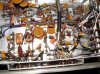
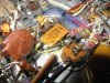
Alright first up is picture #1:
Circled in green are 10 ohm 1/4watt flameproof cathode resistors installed for safety.(They replace nothing, and are installed to protect important/expensive parts by acting as fuses.)
Circled in yellow are the grid resistors. Apparentley for original fisher tubes the original 330k resistors will do just fine. But if you plan on installing new tubes this step is a must!! It will stop your amp from oscillating and/or being unstable. Replace with 220k resistors.
In blue are the coupling capacitors. They are originally .047, but if you switch the grid resistor value to 220k it is necessary to replace with .1 uf to keep/boost low frequency response.
In red are caps that I did not replace. But Maybe should be replaced......you can figure those values out for youreself.
Step 1 parts needed:
4x10ohm 1/4watt flameproof resistors
4x220k 1/4watt resistor
4x.1 uf 630volt Good quality coupling capacitor.
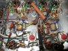
Step 2/ picture 2:
This is the phono/tapehead pre amp section. Located at bottom right corner when looking from the front of the amplifier, already opened up and flipped over.
Here you see 4 coupling caps and alot of resistors. The resistors should be changed if the highest quality sound is desired.(i'll probably do it some time)
In green are .022 250v
In the blue are .01 ??v
So you need:
2x.022
2x.01 (You should just make all capacitors 630volt ones, unless cost is a huuge issue)
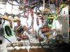
Step 3/Picture 3
Here you see 5 and a half coupling capacitors. And one other ceramic cap circled in red
In yellow .047.
In green .02
The red ones I did not replace, but the ones to the far right definatley have sound pass through them.
I !think! they are .001.
So you need:
2x.047
2x.022
2x.001????
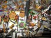
Step 4/Picture 4
This is just a better picture of the half capacitor from picture 3.
I've also cicrcled another capacitor that other people apparently have replaced. I'm not sure of it's value and I did not replace it.
Once you've done this your amp should sound very nice. With slightly deeper bass. The biggest sound difference comes from replacing the ceramic caps. But I enjoyed changing all of them and listning to the difference along the way.
Now the last picture is the bias supply. Many people have wrote how to change the bias from -17 to -20 and said that rebuilding the bias causes a 27 volt to be fed to 12ax7 heaters. Well its all true and all the voltages affect eachother.
So listen close here cause this is the real deal. On how to get everything into spec.
Firstly, replace bridge rectifier circled in yellow.(this is a must!! if you have the selenium rectifier) Mine was a newer Silicone rectifier already so I did not change it.
Second, in green are 1000uf 35 volt capacitors. The ones shown are the new ones I installed.(originally its a very large yellow multicap)
Third, in pink/purple is a 100 uf 25v cap....replace it.
Fourth, This step is actually two steps that must both be done before repowering..... In red is a 15 ohm 5 watt resistor. This resitor will change the 12ax7 heater voltage. I've read that it should be changed to 20 ohm. I did this and it was not enough. In reality you need 25 ohms to bring it down to 24 volts. And if you change this resistor you will affect the bias supply! It would probably drop to -15 volts! So circled in blue is the resistor that controls the bias voltage.(It's hidden behind the wire) You wanna change this to 3.3-3.7k This will get you to about -18.5-20.5 volts.
Now my line voltage is 120 vac. So 20 ohms may work for some people! Maybe!.... But if your heater voltage is 27 after steps 1-3 then I don't see why things would be any different.:yes:
Update: If you have a variac and one of the hgiher model # fisher 400s(it may apply to all of them I'm not sure) You want to set the variac to 115.4 vac wild the amp is powered on. This will put the output tube heater voltages at exactly 6.3 volts, giving longer tube life and more listening hours
ALSO: Using a 22 ohm resistor for adjusting the 12ax7 heaters is just about perfect. After adjusting the wall voltage to 115.4 you have 23.75 volts. very close to the 24 it is supposed to be.
More pictures coming!!
Attachments

Last edited: