• The move to the new server is done. There are some software and database maintenance updates in process. This has us passing the hat around to help out. We appreciate any donations. Seriously, even a dollar helps. The payment page may be found here - https://www.audiokarma.org/support.html

Scott 222a questions..

pfunk951

Old School
Greetings all,

Christmas was good to me, as my Father in Law took me into his audio vault and handed me my first tube amp, a Scott 222a in exceptional condition. He must have deemed me worthy of the transition from solid state, as I have always been hinting at valves but have never made the move.. So here's the meat and potatos of it:

Again, great condition, but this baby has not seen electricity since Nixon was in the White House. Cover is off, and the schematic looks pretty stratght forward, but I have been hearing a wide variety of opinions of what would be a good game plan for a good overhaul. More specifically:

-What brands to use for the underside caps.. I hear that using the wrong brand can destroy the sound.

-Is it worth it to restuff the cans on the topside?

-No rectifier on this model? Didn't see it..

-Anything else I am forgetting to replace that helps the sound?

-Anything mandatory that I am forgetting before a low power tryout on the vairac?

I am nearly fluent with modding solid state gear, which I believe puts me at a beginner/ intermediate stage for this amp. I does look different down there, but I am comfortable with the layout. I am very, very exited about this project and can't wait until I can show it off to my Father in Law..

Thanks in advance, I am off to get these tubes out (yes, they are labeled), and find a power cord to repalce this... brown twine looking thing coming out of the back of the frame.:)

Tube Newbie Mike

BTW... I am going to polish this friggin thing until I need sunglasses to look at it!!!!!!!!!!!!!!!!!!
 
Last edited:
Register to hide this ad
I rebuilt a Scott 222B a few months back. I think this is
the same basic circuit as the 222A. Attached a couple of
before/after pictures showing the under chassis caps which
were changed. The second and third are the after rebuild
pictures. I used CDE WMF coupling caps, these are mylar
which are very similar to the original caps.

Also replaced the cans with new caps under chassis except
for the main power supply can which I cut open and restuffed.

It would be a good idea to bring the amp up on a variac to
verify it works before starting on the rebuild.

Post some pictures of your amp.
 

Attachments

  • DSCF0090.jpg
    DSCF0090.jpg
    142.2 KB · Views: 300
  • DSCF0201.jpg
    DSCF0201.jpg
    123.7 KB · Views: 265
  • DSCF0202.jpg
    DSCF0202.jpg
    123.8 KB · Views: 254
  • DSC_8715.jpg
    DSC_8715.jpg
    88.6 KB · Views: 224
  • DSC_8717.jpg
    DSC_8717.jpg
    143.9 KB · Views: 280
Last edited:
You can find new can capacitors at Antique Electronic Supply or Triode Electronics that will drop right in and look just like what is in there. Your amp is cathode biased and has the preamp tube filaments as part of the cathode circuit of the output tubes. Thus the reason for no bias rectifier. All electrolytic capacitors must be changed in these old Scott amps. As for coupling capacitors, any quality metalized poly type will work well. Super high end capacitors tend to make these amps sound a bit more clinical then some people like. For a warmer sound, the Russian surplus paper in oil capacitors work well. But to me, using these through out the amp tends to make it sound too dark on the high end. But that's just my opinion. You need to let your own ears decide that one. Xicon metalized poly caps sound about as close to the original Cerecaps as anything.
Now, if this amp is old enough to use those black capacitors, just about anything will sound brighter save for the Russian oil capacitors. It would also be a good idea to replace all the plate feed resistors while you are in there. This amp is no harder, if as hard to work on then any solid state amp. It's a lot easier to get at parts in this thing then in something like a Marantz 2500 or a vintage Pioneer solid state amp. Also, since there are no voltage regulator circuits and such, you can bring the thing up slowly with a variac and actually have it start working at voltages as low as 50 - 60 volts on the variac. Most transistor amps using a complimentary circuit will hum like crazy at such low voltages. Tube amps are a lot more forgiving of stupid mistakes. Just be careful of the much higher voltages present in tube amps.
 
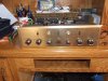
Thanks for the info- here are a few pics of what I am dealing with...

Mikey- I will take a look at the 222b schematic and look for any differences.. I haven't cut anything yet, so I will get this on a Variac tomorrow morning and see what shakes out. Thanks for the pics- looks like you have already been down the road I am embarking on.. I will be piggy-backing your idea of the CDE couplers.. What kind did you use on the main power supply?

Seta- Thanks for the info on the rectifier- I hear that these can be a problem... Glad I don't have one.. I will start looking into caps and get an order in tomorrow.. I am off to Triode Electronics after I post this..

Please let me know if anything looks out of order under the chassis- I am used to looking at circuit boards and am finding myself chasing these wires down with the schematic hoping that I didn't miss anything.. It seems that a mistake is easier to be made under here, so I will be doing this one cap at a time...!


Thanks again for all the help!

Tube Newbie Mike

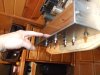
P.S. The last picture is just a glamor shot- take a look at the reflection of my finger... I figure I will be waiting for the caps so I might as well start polishing..!
 

Attachments

  • DSCF7827.jpg
    DSCF7827.jpg
    67 KB · Views: 201
  • DSCF7826.jpg
    DSCF7826.jpg
    135.3 KB · Views: 197
  • DSCF7821.jpg
    DSCF7821.jpg
    94.4 KB · Views: 177
  • DSCF7822.jpg
    DSCF7822.jpg
    87.7 KB · Views: 189
Last edited:
Great looking amp! Nice work. As you increase voltage, pay attention to the temperature of the power cap, (immediately behind the PTX). If it starts to warm up at all, shut it down and replace it before you do anything else. Don't want to risk burning out the PTX and the very valuable rectifier tube.
 
One difference I see is that the 222A doesn't use a bias voltage adjust pot
like the 222B. This adjusts the DC voltage across the 12AX7 filaments which are
wired in series. The 222A must control this voltage by fixed resistor values.

For the restuffed main PS can I used Nichicon caps purchased from Mouser.
Except for the first 20uf capacitor after the rectifier. For this one I
used a F&T 22uf 500 VDC purchased from AES (tubesandmore.com)
and mounted under chassis because of its larger size.
The first capacitor after the rectifier takes the brunt of the power
surge when turning on the amp and I wanted a higher voltage rated
capacitor in this position. For the other three in the main power supply
can I used Nichicon 22uf 450VDC (UCS2W220MHD) because these have
a high ripple current rating. For the other three cans I used a mixture of
Nichicon and Sprague Atom caps all mounted under chassis.

One thing I will mention, restuffing the main PS can was a bit of
work......so its probably easier to just buy a new can from AES
for this, and then use under chassis caps for the other three cans.
For the main PS can, this one on AES site should work, C-EC20X4-475
and its only $31 ......
 
Last edited:
Got yourself a nice amp there, for caps I used Mojo's Dijons Cap's from
Mojo Musical Suppy. there in my LK48 and LK72 Scott's and there really nice
and they fit under the chassis as well, Check all resistors and replace the
electrolytic's as well, just take your time with it, because in the end they all
sound great! :music: if done right and there's a lot of help you can get here
on this site when you need it. :thmbsp: here's a picture of the Scott LK48
with all new Caps in it.

Tube
 

Attachments

  • IMG_5058.jpg
    IMG_5058.jpg
    114.3 KB · Views: 154
OK,

I am set up for a noon test on the variac- will keep an eye on the power supply can to make sure she doesn't heat up..

I am going to put in an order on the coupling caps (I count 17) and was wondering: should I stay with the stock values? For some reason I think I remember someone saying that you can go higher.. But then I could be hallucinating- I have been reading so much info on tube amps lately that I'm sure that I am crossing thoughts..

I have officially worn my fingerprints completely off polishing this thing.. About 50% finished.. And it is looking good..:thmbsp:

Thanks again guys!

Mike
 
Hi,
I would stay with the stock values but going up on voltage is better, like
if you have say a .047 400Volts you can get a .047 600 or 630volts, I usual
stay pretty close unless that value is not available and have to go up one.

Tube
 
There are several different options for the coupling capacitors....
and these caps are the thing that will affect the sound the most.

I did lot's of reading up on the different options and decided to use the
CDE-WMF capacitors. These are polyester-film (mylar) and apparently
are the most similar to the original caps. According to
some info I read..... Scott optimized the circuit in these amps to
work best with mylar capacitors. There's some good info on the
following link (from Hot Glass Audio post):

http://www.audiocircle.com/index.php?topic=36516.0;wap2

Some other forum members prefer the Russian paper in oil caps
which can be ordered from the auction site, but may take awhile
to receive. I decided to stay with the Mylar caps based on the
info I found. I also stuck with the original values .1uf/400V.....
My goal was to preserve the original sound of the amp.
 
Last edited:
OK,

I am set up for a noon test on the variac- ....

Mike

Let us know how the test goes. Knowing the amp works before starting
the rebuild is a big advantage. This way you can replace a few parts,
then power on to make sure it still works, etc.

Unfortunately my 222B didn't work before the rebuild.... and it didn't work
after the rebuild either :-(
I had to spend an additional few hours troubleshooting to finally figure out
the bias pot was bad....argh
 
There are several different options for the coupling capacitors....
and these caps are the thing that will affect the sound the most.

I did lot's of reading up on the different options and decided to use the
CDE-WMF capacitors. These are polyester-film (mylar) and apparently
are the most similar to the original caps. According to
some info I read..... Scott optimized the circuit in these amps to
work best with mylar capacitors. There's some good info on the
following link (from Hot Glass Audio post):

http://www.audiocircle.com/index.php?topic=36516.0;wap2

Some other forum members prefer the Russian paper in oil caps
which can be ordered from the auction site, but may take awhile
to receive. I decided to stay with the Mylar caps based on the
info I found. I also stuck with the original values .1uf/400V.....
My goal was to preserve the original sound of the amp.

Thank you for the info.

Tube
 
@mikey99,

I read the link that you cited, and found it interesting, although not entirely convincing. How does Hot Glass Audio "know" Scott's design intentions . . . unless he was part of the original team, or has some documentation from the company?

If you were a designer, how specifically would you adjust circuit values to "compensate" for the "sound" or characteristics of a particular capacitor? Why, you'd most likely take the "path of least resistance" (sorry) and let NFB do its thing . . .

AFAIK, there were not the plethora of capacitor choices back in the days when Scott designed their products. The old timers might have laughed at the notion of an "audiophile grade" capacitor.

I suspect that new technologies would have given the original designers -- as well as the tweakers and restorers who followed them -- new choices to try and perhaps make improvements therewith.

Just sayin'

Buzz
 
I used the WMF caps mainly to preserve the original sound
and also because they were readily available. Others have
used the Russian PIO caps in 222B amps with good results.
You can use any coupling cap but until you experience the
original sound (or closest thing to it) you have nothing to
compare it to.

You could try changing out the coupling caps in only one
channel.... that way you can easily compare the differences.
 
I guess the ability to hear the "original sound" would require that all of the caps be good . . . if that were the case, there would be not be so much of a reason to change them.

;-)
 
I guess the ability to hear the "original sound" would require that all of the caps be good . . . if that were the case, there would be not be so much of a reason to change them.

;-)

That's like resistor color codes. There's no reason to read them until they're burned out and you can't.
 
Of course not. I often find lots of discrepancies between SAMS schematics and actual builds. Sometimes manufacturers changed parts because of shortages or circuit redesigns, which weren't reflected in the print.

I was being a (good-natured) smart-ass, Mikey. :banana:
 
OK!

Got her on the variac a day late, 30 min at 50 volts. Worked great... Upped it to 80 and the can behind the power supply started to heat up, so we powered down and called it off until I got some input from my support team (you guys).

Time to restuff the can? If so, I could wait until my caps show up and do a 1 day tear down/ recap of the couplers while taking care of the can..

Mikey/ all: is there any benefit to just buying a new can vs restuffing? I am very familiar with those Nichicon caps you spoke of.. Will I be getting the same quality with that can you spoke of..

Thanks again guys, it looks like this project is off the ground and on it's way.. Must keep polishing... Heh..:thmbsp:

Mike
 
Back
Top Bottom