• The move to the new server is done. There are some software and database maintenance updates in process. This has us passing the hat around to help out. We appreciate any donations. Seriously, even a dollar helps. The payment page may be found here - https://www.audiokarma.org/support.html

We can rebuild him. We have the technology...

Watthour

Electron Rancher - JS3600
Subscriber
Mr. Noble, that is. A.K.A., the "Six Million Dollar Switch" to small SX-x50 owners.

I picked up a fairly clean SX-750 and the switch had been jumpered previously. I didn't want to operate it by plugging in or via a power strip, so there was little choice but to replace or repair the switch. If you have ever searched for one, you might understand the reason to do what follows.

The switch can be removed from the rear of the speaker selector rotary decks. Once the bottom is off the unit and face plate removed, the switch can be removed and exposed without unwiring. Desolder the leads and MOV-X/Y capacitor, then remove the power switch from the speaker selector stack. The rivets holding the switch body to its metal mount are aluminum, and can be re-formed and driven from the plate to allow opening the switch.

[/IMG]SX-750PowerSwitch03.jpg

With the switch open the plain toggle mechanism can be observed and the damage can become apparent. In my case, the stationary contact (a simple copper post) was heavily pitted and the connection between the copper post and its solder lug had become loose, allowing intermittent contact. The stationary copper contact can be rotated and re-staked to the solder lug, then soldered in place securely. The movable contact on the toggle arm can be cleaned acceptably, and the switch can then be reassembled.

SX-750PowerSwitch02.jpg

SX-750PowerSwitch01.jpg

In my case, that solved the problem completely. I may eventually install a relay to take the main power load and have the switch pilot the relay only, but I should have just bough myself a few more years on the switch contacts.

It appears that a variation of the Noble rotary switch is still available, but appears to be attached to a potentiometer:

http://www.analogmetric.com/images/200906/1246134414828393003.jpg

1246134414828393003.jpg


Looks like it can be found --->HERE<---

In the future I may have to investigate the viability of using one of thee potentiometers as a donor for the Pioneer power switch application. In the interim, if you are reasonably skilled you can probably do as I did and repair what you have before it is beyond recovery.

EDIT: Update photo links
 
Last edited:
Register to hide this ad
Why not wire up a relay to take the load off the switch? This way the relaytakes the hit on powerup and the switch only has to carry enough current to turn the coil in the relay on. :scratch2:
 
Good suggestion. I mentioned that about halfway through the post. I have a couple of flange mounts on order, since I have a few units with this switch (450/550/750) and some others with the Alps rotary switch which can suffer a similar problem.

70198617_left.jpg


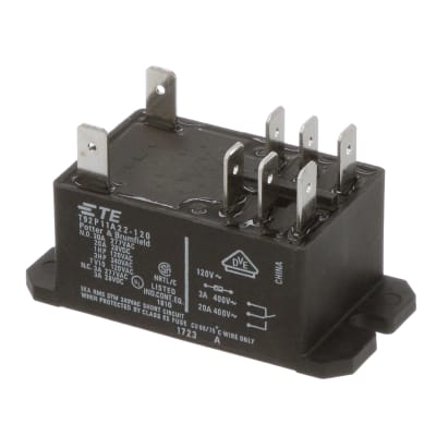
At 1" x 1" x 2-3/4" it should fit along the transformer on the chassis side rail or on the rear panel easily. I chose a flange mount for flexibility, and can solder to the lugs. I'm confident in the 30A contacts (resistive, 1200 VA inductive) but I'll try one to check the noise level on holding. I don't want any buzz or hum, and some of the Magnecraft will do that on AC, whereas most Omron and P&B are fairly silent. If it's not silent I'll use them on a different application and keep hunting.
 
Last edited:
The install is cake. The two 30A contacts are now bridged, so I doubt that even in a primary winding fault the relay is going to struggle. The original main power switch is now taking it easy, switching a miniscule 4 watts to pull in the armature. I can now safely use a 1000W coffee maker or hair dryer on the switched outlet on the back and not worry. The relay is dead silent once it pulls in with a reassuring slap - There is no doubt it has turned on.

The wiring was easy enough to keep away from the lower level audio circuits (105°C white wire w/tracers):

SX-750PowerRelayWiring.jpg


Fitment was easy via two M3-0.5 x 6mm HWH screws through tapped holes in the back plate. They are only accessible from the inside so there is no way to accidentally unmount it.

SX-750PowerRelayMounting.jpg


I covered the terminals with tape as a precaution since I didn't have a silicone cap that fit that size relay. I have a spare to use as a gauge to find an appropriate cap or cover, and then the spare will go in my Kenny with an Alps switch which has already been resurrected once.

If you have the space, this seems to be a decent relay to use for up to 60A (30A per pole). There is also a single pole version which would probably be suitable and it is slightly smaller.

EDIT: Updated photo links
 
Last edited:
Nice mod, I like the mounting particularly.

I did something similar with an SX-650 a couple of years ago but the relays I had were larger and I ended up having to locate it behind the upper left end of the faceplate. Would have preferred to keep it more in the power supply area but it just didn't fit there.

I don't see the arc-suppression cap anywhere though... did you leave that at the switch? Would have thought it would be better suited to handling arcing at the higher current contacts of the relay, since you've shifted that away from the switch. I guess even at the switch there could still be some minor arcing due to the inductance of the relay coil... but I only had one of those handy to use (the original) so I relocated it to the relay.

John
 
The original cap is still mounted across the switch, and there is another cap at the power connection/voltage plug area. It's a little tough to see in the first photo but it's buried there in that well.
 
This is awesome. Well done Watthour!

I really want to (eventually) do this to my SX-750. Forgive me, but Im having trouble figuring out how you wired this Relay from your pictures. I have beginner/Intermediate experience with building/fixing electronics, but I am just not 100% sure on how you integrated this into the existing circuit, and Id like to avoid butchering this whole thing up (if possible, haha).

I can see that you ran wires from the switch here back to the relay coil, then from the relay contacts back to the outlet(s).
Im just not sure where you went with the wires from the relay contacts back to the outlets. Did you cut any wires, or did you do everything point-to-point on the outlet contacts?

Also, I dont fully understand what you mean by:
"The two 30A contacts are now bridged, so I doubt that even in a primary winding fault the relay is going to struggle"
Did you use the 2-pole relay to go to each individual outlet, or when you 'bridged' it did you mean that you simply use the relay as a single-pole relay and connect it to the 'switched' outlet only, leaving the first 'unswitched' outlet unswitched? If so, which contacts did you bridge specifically on the relay? Did you do that to make it more robust?

For the arc protection caps, when you said: "there is another cap at the power connection/voltage plug area." is that the original one relocated, or did you add a new cap into the circuit there?

I think I have the general idea figured out, but if you could confirm these few things, it would help confirm that Im understanding it correctly.

Thanks for any info you can provide! I really appreciate it! :)

K

Relay Wiring Snip.PNG
 
For clarification, C3 is factory installed at the switched receptacle to alleviate spikes. C4 was left installed across the power switch to protect the switch itself, although the switch is now only operating the power relay coil.

The relay used was a DPDT with 30A inductive rating for each contact These contacts were wired in parallel, theoretically allowing a 60A load without problems. Thus, even the switched receptacle can now handle current up to the limits of the power cord itself and the branch circuit rating instead of the original 100W limit.

All wiring was terminated on the existing factory solder lugs at either the receptacles or the switch. This is how the circuit was modified:

SX-750PowerRelaySchematic.jpg

EDIT:Updated photo links.
 
Last edited:
Fantastic! Thanks for the detailed info!! :thumbsup:

Is this something that one should consider doing because of the durability issues associated with the rotary power/selector switches on these receivers, or is that just something you did because you wanted to use those rear outlets on the receiver?
 
I did this so that the somewhat frail original power switch would outlast the rest of the unit. Search the forums (fora?) and you will likely find hundreds of thread about failures of these switches.
 
Yessir. It still has a nice, resounding CLAP when powering on, then the reassuring faint Click of the protection relay several seconds later. The switch in now handling about 120mA pull-in and 50 mA holding current. I think it will wear out mechanically before it ever fails electrically, and given that it is a cam/leaf system that should be long after I'm gone.
 
Thats so badass, haha.

And yeah Watthour, Ive read about the poor power switch reliability. Sorry, I didnt mean to give the impression that I hadn't researched it at all. I was just curious if you had plans to frequently use those outlets, or if you were just making that thing BOSS, haha.

Glad its still CLAP'n for you!! Ill be trying to replicate your sweet modification here, once I get my 750 back on track. I think Ill be doing a re-cap on it, but thats for another thread.

Thanks again for all the great info. The schematic you provided is much appreciated!!
:beerchug:
 
Hey again Watthour, I hate to bug you about this, but I think that one of the pictures you had Originally Posted in Jun 2011 may have been replaced by your recent schematic?

I thought that you may have had another picture of your wiring to/from the relay, (maybe from the bottom of the unit, showing the switch if I remember correctly?), and I was just looking for it to reference it. It looks like maybe it was replaced by the schematic picture that you just showed to me recently in Oct 2016?

I was just curious if you still had that picture somewhere on your account so that I could reference it? Or maybe you can re-upload it? (Sorry, I know thats kind of a lot to ask). I am just wanting to reference it, so that I can make sure that I dont muck this whole thing up.

Thanks again for any info you can provide! It means the world to a novice like me.

-K
 
Good catch! Thanks for the note. I'll try to correct my web archive (file overwritten - corrected).

Unfortunately I can't seem to repair the links in the other posting.
 
Last edited:
Thanks for looking into this!

Im in the middle of my recap now, so Ill have the front panel off, and I might as well do this mod while Im in there. Having that picture to help me along will make a tremendous difference.

Silly, rookie question though: How can I access that picture on your web archive? I tried doing a search on AudioKarma for Web Archive, but I didnt come up with much. Do you have your own website where you archive everything?

Thanks again. As always, your time is much appreciated.

-K
 
FYI to anyone else with this issue with the pictures not appearing correctly:

I had to clear my cache to see this pic correctly. I finally tried to view it in Internet Explorer, and it appeared. After clearing my cache in Google Chrome, it appeared. My mistake. :p

Credit to Watthour for steering me straight on this.

Hopefully this helps someone else out if they find they are having similar issues. :)

Thanks,

-K
 
Last edited:
Back
Top Bottom