


Freezer7Pro
Luxman!
A while ago, I received a shipment of cheap 5mm LEDs for another project. Upon finishing it, I had about twenty left, which reminded me of my rather sad-looking baby Pioneer:
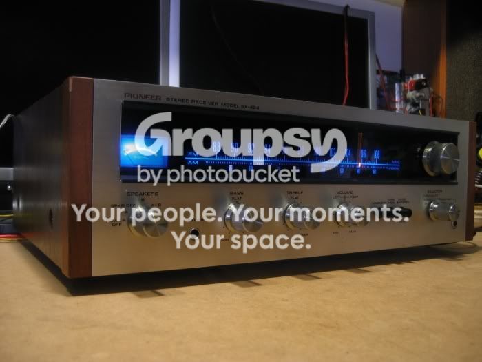
You can literally see the frown on its face, can't you?
While the cheap LEDs are a bit too blue in colour for most other lighting projects I've got going, I figured that they'd fare quite well in the already blue-filtered face of the 424, and thus, the work commenced!
I started by making a little 5-led row, which I placed in the bulb compartment, aimed away from the front as a preliminary test. I was pleasantly surprised when it seemed to work great without me having to make a new light spreader.
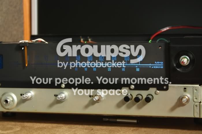
The temperature of the LED light is not by any means the same as that of the original light bulbs, as demonstrated by the below picture. However, I wouldn't at all be surprised if the LED light is closer to what the original designer had in mind. After all, it is a lot less green, and more purely blue.

After that successful proof of concept, I proceeded to make a 9-piece LED string:
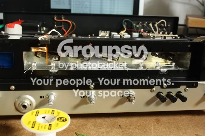
...which even worked! You can see some of the LEDs I had to discard due to them being DOA, lying to the left of the string.
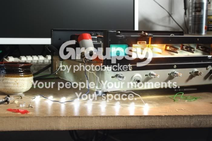
After successful testing, I mounted them inside the bulb compartment using hot glue. (We Finnish love hot glue, for some reason :yes: )
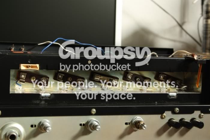
Let there be light!
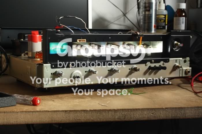
It looks like there's some kind of reactor in there. Those cooling vents aren't going to do much good anymore.
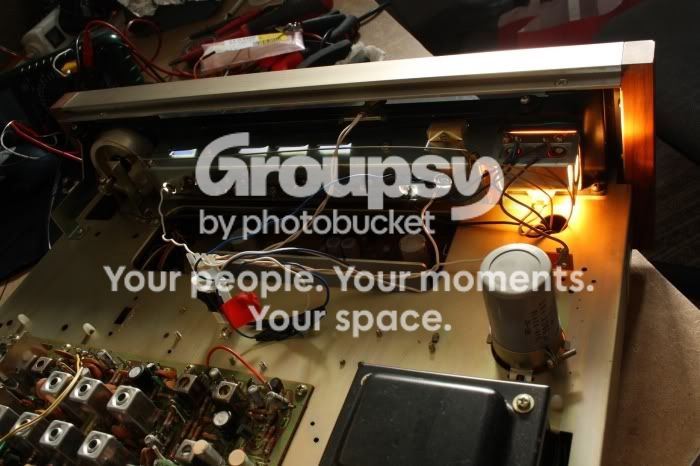
Putting the face back, it is clear that the project has been a success:
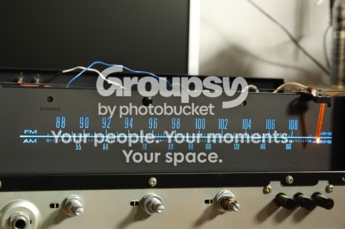
...and the frown got wiped away!
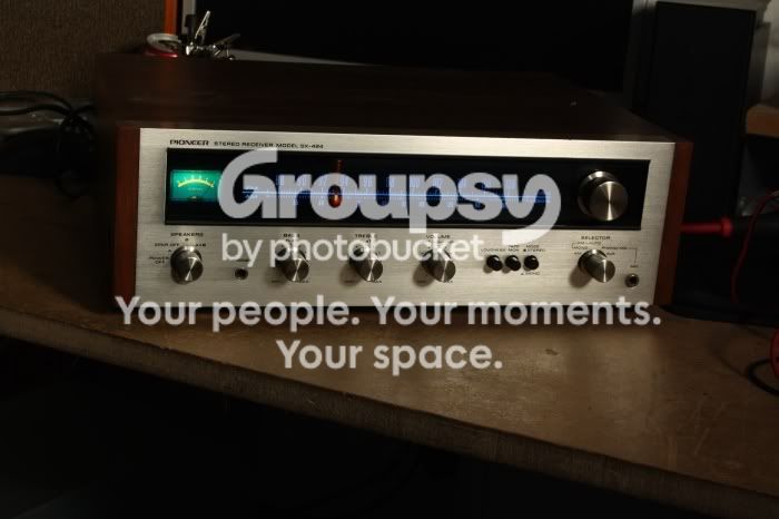
I can finally put this guy in use somewhere without that dark faceplate annoying me.
And if you're wondering, the changes are of course 100% reversible. It's just to put the bulbs back in and remove the wiring for the LEDs if one wants to go all original in the future, for some reason.
EDIT: Made clickable thumbnails rather than humongous beasts of pictures right in the forum. So, go ahead and click the pictures for... Much larger versions.

You can literally see the frown on its face, can't you?
While the cheap LEDs are a bit too blue in colour for most other lighting projects I've got going, I figured that they'd fare quite well in the already blue-filtered face of the 424, and thus, the work commenced!
I started by making a little 5-led row, which I placed in the bulb compartment, aimed away from the front as a preliminary test. I was pleasantly surprised when it seemed to work great without me having to make a new light spreader.

The temperature of the LED light is not by any means the same as that of the original light bulbs, as demonstrated by the below picture. However, I wouldn't at all be surprised if the LED light is closer to what the original designer had in mind. After all, it is a lot less green, and more purely blue.
After that successful proof of concept, I proceeded to make a 9-piece LED string:

...which even worked! You can see some of the LEDs I had to discard due to them being DOA, lying to the left of the string.

After successful testing, I mounted them inside the bulb compartment using hot glue. (We Finnish love hot glue, for some reason :yes: )

Let there be light!

It looks like there's some kind of reactor in there. Those cooling vents aren't going to do much good anymore.

Putting the face back, it is clear that the project has been a success:

...and the frown got wiped away!

I can finally put this guy in use somewhere without that dark faceplate annoying me.
And if you're wondering, the changes are of course 100% reversible. It's just to put the bulbs back in and remove the wiring for the LEDs if one wants to go all original in the future, for some reason.
EDIT: Made clickable thumbnails rather than humongous beasts of pictures right in the forum. So, go ahead and click the pictures for... Much larger versions.
Last edited:


