


Zonker92
All shiny and chrome
Recapping JBL 250Tis - Finally Done
My goal here was to upgrade the L250Ti caps, signal-path resistors, the the woofer coil. I tried not to spend a fortune but achieve good results while keeping the specs original. Note the even those these crossovers came out of sequentially numbered speakers, one of the boards is tan and the other is blue. Also, at least one of my "before" photos is generic (from another poster).
Here is the schematic:

(R3 is missing, but it's 5.1 ohms on the 108H shunt.)
Here is how the board looked originally:
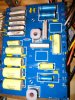
Removing the caps from the board required some leverage, as they were glued down. I heated a metal putty knife blade with a propane torch to scrape off the hot glue residue. (I don't have an "after" shot on the glue.)
I put the boards on a piece of plywood with a metal strap to support them, so I wouldn't keep flexing the wires (at the top left below you can see a 24 uF Solen that I wound up replacing with parallel Jantzen Standards (22 uF + 2.2 uF), because the last two Solens I needed were out of stock):

Most of the components are marked clearly, but not the off-board resistors. I wound up sliding a razor blade between them to cut the glue, then using a metal putty knife gently to force them apart slightly, then shining a light between them to read the numbers. After a lot of rumination and second-guessing, I finally figured out which was which. From top to bottom (that is, with the writing on the board oriented properly), they are:

I replaced the signal-path resistors (and, by accident, one of the attenuator resistors) with Mills 12-watt resistors. I replaced the shunt caps mainly with Jantzen Standards, and a few Solens and Jantzen cross-caps, of the same value. I replaced the signal-path tweeter cap (2.7 uF) with a Jantzen Silver, the 104H midrange cap (10 uF) with a Jantzen Superior, and the 108H mid-bass driver (40 uF) with parallel ClarityCap SAs (39 + 1). I bypassed every cap (or set of parallel caps) with one Audiocap Theta .01 uF. I replaced the 6.0 mH woofer coil with an ERSE Super-Q of the same value. I bought everything from Parts Express except the resistors (Parts Connexion), ClarityCaps (Madisound) and some of the Thetas (Opentip). It was NOT cheap. The ERSE coils are $25 a pop. The resistors and bypass caps are over $4 each. The higher-end Jantzens and the big ClarityCaps are around $50. Apiece.
I mounted the new coil on some plywood, stacked up and screwed to the crossover board. I glued everything down with Goop and replaced the original tie-wraps.

It's been a month since I started this project, so I can't say I really remember precisely how they sounded before, and I now have a "new" Adcom GFA-5800 amp (250WPC) driving them, but I do like how they sound now.
(I posted this over on L-H, too.)
My goal here was to upgrade the L250Ti caps, signal-path resistors, the the woofer coil. I tried not to spend a fortune but achieve good results while keeping the specs original. Note the even those these crossovers came out of sequentially numbered speakers, one of the boards is tan and the other is blue. Also, at least one of my "before" photos is generic (from another poster).
Here is the schematic:
(R3 is missing, but it's 5.1 ohms on the 108H shunt.)
Here is how the board looked originally:
Removing the caps from the board required some leverage, as they were glued down. I heated a metal putty knife blade with a propane torch to scrape off the hot glue residue. (I don't have an "after" shot on the glue.)
I put the boards on a piece of plywood with a metal strap to support them, so I wouldn't keep flexing the wires (at the top left below you can see a 24 uF Solen that I wound up replacing with parallel Jantzen Standards (22 uF + 2.2 uF), because the last two Solens I needed were out of stock):
Most of the components are marked clearly, but not the off-board resistors. I wound up sliding a razor blade between them to cut the glue, then using a metal putty knife gently to force them apart slightly, then shining a light between them to read the numbers. After a lot of rumination and second-guessing, I finally figured out which was which. From top to bottom (that is, with the writing on the board oriented properly), they are:
I replaced the signal-path resistors (and, by accident, one of the attenuator resistors) with Mills 12-watt resistors. I replaced the shunt caps mainly with Jantzen Standards, and a few Solens and Jantzen cross-caps, of the same value. I replaced the signal-path tweeter cap (2.7 uF) with a Jantzen Silver, the 104H midrange cap (10 uF) with a Jantzen Superior, and the 108H mid-bass driver (40 uF) with parallel ClarityCap SAs (39 + 1). I bypassed every cap (or set of parallel caps) with one Audiocap Theta .01 uF. I replaced the 6.0 mH woofer coil with an ERSE Super-Q of the same value. I bought everything from Parts Express except the resistors (Parts Connexion), ClarityCaps (Madisound) and some of the Thetas (Opentip). It was NOT cheap. The ERSE coils are $25 a pop. The resistors and bypass caps are over $4 each. The higher-end Jantzens and the big ClarityCaps are around $50. Apiece.
I mounted the new coil on some plywood, stacked up and screwed to the crossover board. I glued everything down with Goop and replaced the original tie-wraps.
It's been a month since I started this project, so I can't say I really remember precisely how they sounded before, and I now have a "new" Adcom GFA-5800 amp (250WPC) driving them, but I do like how they sound now.
(I posted this over on L-H, too.)
Last edited:


