• The move to the new server is done. There are some software and database maintenance updates in process. This has us passing the hat around to help out. We appreciate any donations. Seriously, even a dollar helps. The payment page may be found here - https://www.audiokarma.org/support.html

Kenwood KR-6050.. no coffee yet?

69B-Cuda

Member
Hi all, I have a Kenwood KR-6050 that I recently got off Craigslist. I did the normal cleanup of all the controls and it works well except for 2 small issues that I could use some help on.

1. When I first turn it on, it takes 3-4 minutes before the relay kicks in and it will play any sound. Almost like me in the morning before having my first cup of coffee! (after it has been on for a bit, this is drastically shorter, maybe only 10-15 seconds...)

2. It seems like one channel is slightly quieter than the other. ( I know, could be anything)

Other than those issues, it is a nice unit and I am quite happy with the 30$ I spent on it. I may do a recap though one of these days.... just because....
 
Register to hide this ad
The KR-6050 sounds great. I repaired one that belong to my former boss. I first received it and I thought it sounded like pffft. But after replacing a couple bypass caps, it sounds so good that I couldn't turn it off. Later, I bought one for myself. It appears my amp is overshooting so will fix later. You'll love it once you get it working right.
 
The 6050 is a decent little unit. I salvaged mine from the dead and think it has a lot going for it.

Where is the offset voltage? What about the power supply voltages? I'm thinking that something isn't playing well with others until it gets warm, and that shouldn't be the case.
 
I will measure the offset voltage tonight. Where do I measure the power supply voltage at, and what should it be?

Also, do you know where to measure the bias current? the manual I have says what it should be but not where to measure it... ( I just did my Sansui 9090DB so I am familiar with the process).
 
From the manual:

BIAS CURRENT
The KR-6050/6650 has no trimming potentiometer for adjusting the bias current. R1(R2) and/or R3(R4) of the power amp section (X07-1700-10) are used in place of trimming potentiometers.

It is necessary to check the value of the bias current when power transistors, driver transistors and/or varistor diodes are replaced.

The bias current must be within the range of 20~200 mA*
(The recommended value is 40 mA). If not so, change the value of the resistors above mentioned.

* The DC voltage between the terminals 15(17) and 16(18) (X07-1700-10) must be within the range of 4.4 mV~44 mV.
 
From the manual:

BIAS CURRENT
The KR-6050/6650 has no trimming potentiometer for adjusting the bias current. R1(R2) and/or R3(R4) of the power amp section (X07-1700-10) are used in place of trimming potentiometers.

It is necessary to check the value of the bias current when power transistors, driver transistors and/or varistor diodes are replaced.

The bias current must be within the range of 20~200 mA*
(The recommended value is 40 mA). If not so, change the value of the resistors above mentioned.

* The DC voltage between the terminals 15(17) and 16(18) (X07-1700-10) must be within the range of 4.4 mV~44 mV.

OK, measuring the offset at the speaker terminals, 128mv on left and right sides. I read the bias current info in the manual... is that saying that 20~200mA is measured by measuring voltage between 15(17) and 16(18) and having it in that range?
 
Primary power supply voltages can mostly be checked on the Audio board, (X09-1350-10).

Referenced to a good chassis ground, Pins 27 and 28 should each have ~33VAC, or 66VAC between the two. This feeds the bridge rectifier supplying just about everything but the dial illumination.

Pin 8 should have +46VDC. Pin 10 should have -46VDC. Pin 12 should be +1.25VDC. Pin 13 should be -1.25VDC.
 
Offset is different than bias current.

To check offset, connect the meter leads to the speaker "A" terminals Turn the selector to the speaker "A" position so your meter reads the voltage. Voltage should be set as close to zero as possible. Adjust the Left and Right channels with trimmers VR5 and VR6 on the main audio amp board to achieve the lowest reading.
 
Offset is different than bias current.

To check offset, connect the meter leads to the speaker "A" terminals Turn the selector to the speaker "A" position so your meter reads the voltage. Voltage should be set as close to zero as possible. Adjust the Left and Right channels with trimmers VR5 and VR6 on the main audio amp board to achieve the lowest reading.

I understand the difference... reading my post, I ran the 2 together...

I measured the offset at the speaker terminals, ~128mv on left and right sides.

I read the bias current info in the manual... is that saying that 20~200mA is measured by measuring voltage between 15(17) and 16(18) and having it in that range?
 
Primary power supply voltages can mostly be checked on the Audio board, (X09-1350-10).

Referenced to a good chassis ground, Pins 27 and 28 should each have ~33VAC, or 66VAC between the two. This feeds the bridge rectifier supplying just about everything but the dial illumination.

Pin 8 should have +46VDC. Pin 10 should have -46VDC. Pin 12 should be +1.25VDC. Pin 13 should be -1.25VDC.

sweet thanks for the info! I"ll have to take the top off and have a look-see!
 
Primary power supply voltages can mostly be checked on the Audio board, (X09-1350-10).

Referenced to a good chassis ground, Pins 27 and 28 should each have ~33VAC, or 66VAC between the two. This feeds the bridge rectifier supplying just about everything but the dial illumination.

Pin 8 should have +46VDC. Pin 10 should have -46VDC. Pin 12 should be +1.25VDC. Pin 13 should be -1.25VDC.

ok, pins 27/28 are at 34.6 v so that is pretty close... I can not find pins 8, 10, 12, 13 on that board though. Are they on a different board? ( I found those #s on X-5-1650-10)
 
Those other pins are in the connectors which couple up the final amp boards. You can also check the ±46VDC on the main filter caps.

Did the DC offset adjustment help the situation at all?
 
OK, I checked this morning after adjusting the DC offset, it still took ~2 minutes to kick the relay in and get power to the speakers. I did listen through headphones and the sound seems the same left to right though...

The dial lights flicker real bad for the first minute or so, like the power supply is not real sure it is going to cooperate... then they are steady once it warms up a bit.. I believe they steady out before the relay kicks in...
 
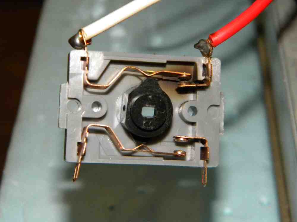
Flickering lights on start up is almost always the power switch arcing. Unplug the unit, jumper the ac switch, then plug it into an outlet strip and turn it on with the outlet strip. They may have been still using the ALPS switches like in the kr-4070, 5030, and 6030. (also a lot of pioneer receivers of that vintage) (grey block with a cap across the contacts).
 
thanks sregor, I'll bypass the power switch and see if that also takes care of my delay upon first startup. Is there a replacement available for the power switch from Mouser or somewhere?
 
sregor is correct. It's the same Alps VR-5 switch used on the other models he listed, as well as other brands.

Since you would have to remove the old switch to replace it, you might want to check this out first:

http://audiokarma.org/forums/showthread.php?t=53495

AlpsVR-5.jpg
 
Back
Top Bottom