• The move to the new server is done. There are some software and database maintenance updates in process. This has us passing the hat around to help out. We appreciate any donations. Seriously, even a dollar helps. The payment page may be found here - https://www.audiokarma.org/support.html

QRX 9001 Restoration (as in "yet another one")

sKiZo

Hates received: 92644 43.20°N 85.50°W
There's various other restoration threads on AK for this receiver, but my goal here is to do a bit more background for clarification of some of the issues I had ... issues with. Not much in the way of "new", but mostly an assortment of odds and ends I dug up and benefited from on the project.

Which by the way, is moving along nicely once again after a year or two off ...

PS ... the real work starts around post #13 ...


~~~~~~~~~~~~

OK ... I've got mods poking and prodding me to start my own thread instead of littering the board with my musings. I hated the poking ... but I didn't mind the prodding. Anyway, here goes with more or less a compilation of where I'm at.

THE VICTIM

qrx9001-original-dial-light.jpg


All in all, real decent machine as is. Cosmetically a 9+, all the dial lights work, all functions and switches good, clean power all channels and modes. It does have the occasional cutouts when switching modes that would seem to suggest the usual pass thru problems when it comes to these things. I also have some noise - more of a heterodyne thing like an out of spec cap run amuk in one channel that comes and goes. Me being a glutton for punishment (yes ... I pick at scabs too) I've been working my way up to diving in. I've got a spare QRX6001 I'm using in the meantime, so I won't be without music. I also practiced on a full recap on a QR4500 that went well, so I got my feet wet there on all things Sansui.

So far, prep work only. Got my caps sorted - first time I've ever had to go with the old tackle box trick, but then this is the first time I've had that many parts to keep track of. I went with the CDE 12000uf50v replacements for the primary power, then Elna Silmic II, Nichichon KZ where available, then KW. In any case, all audio grade. Also plan to do the fusistors as recommended. Thanx and a tip of the hat to XFORMER for the parts list. I was able to do it all in one order from Mouser with a few voltage substitutions.
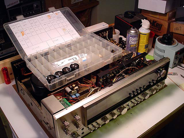
qrx9001restore-caps-sorted.jpg


That pic was a lot more work than it looks. I also rebuilt my bench and added an "L" so I'd have room to work on the beast. Less room to throw things too - which is probably a good thing.

Also ordered up a Weller analog soldering station and ... tada ... (cue the angels singing) ...

cardas-quad.jpg


Got the service manuals, ghosted the boards for a while now, bookmarked a bunch of threads, and I think I'm ready to go. Wait ... one other thing. BALLS!

Lemme see ... a ball of twine to keep boards out of the way, a ball of hookup wire for lights ... :D
 
Last edited:
Register to hide this ad
Yup ... but I figure the bigger they are, the bigger they blow!

Was hoping you'd stumble across this. I was reading up on some of your adventures re: The Big One. I figure this to be a major project and expect it to take a while. Wouldn't bother me much if it took most of the coming winter ... up here in cold country Michigan, it's good to have something to keep the walls from closing in when the weather goes south ... tastefully lighting and photographing a can of solder for instance. Rainy and cold today. <G>

If all else goes well, I'm also thinking about an LED lighting conversion. You still burning the blues? I seem to remember you were having second thoughts. I did find a setup that uses a breadboard power supply that sits in behind the lighting board that looks slick. Guy's done all the homework on color temperatures and matching the original lights for output. Kewl Beans! Parts lists, pictures, testing procedures, the works. I put together a project list on Mouser. They've even got the LM2941T regulator now, so once again, one stop shopping. and it comes up to around $70, including a couple extra breadboards, test clips and such for experimenting.

How to LED Relamp a Sansui ORX-9001

I've also toyed with maybe using LED strips like these:

Linrose 10v light strip

One thing that's always bothered me sometimes is the "black hole" in the lighting on the meters due to the socketing arrangement. I figure you could work around that some with the LED strips. Haven't taken a real close look at the meters yet to see if there's some mechanical reason why the black hole occurs. The strips are super low profile, you can cut them to length, and it looks like there's plenty room to fab up some light duty brackets to glue them to. Play with the spacing, color (gel film or sharpie?) and dispersion some. I didn't see a warm white to emulate the incandescent glow for the power meters, but the standard white could probably be tweaked with gel filters. Same with the green - I'd hate to lose that old school aqua Sui is famous for. Heck - power supply would be a no brainer. Just plug a 9v wall wart into the switched AC jack on the back and run the lead inside. Underpower on the 10v strips might even tone them down a bit so they don't get all gaudy like. Use twisted pair wire to eliminate any interference.

Thing is - the original incandescents are all working fine, so it's not a priority. And they do look good. That said, my old pal Murphy would be bound to rear his ugly head and pop a light or two as soon as I button it up. He's like that, you know.

Long as I'm on the subject of lighting - I'd be interested in finding out if anyone has ever worked the dial panel to eliminate the glow around the edges. Be tricky on the end by the lights, but I've worked a couple projects where some pinstriping tape (or even good old 3m 33) on the edges does kill the glow. Also seems to me I've heard complaints that the light gets dimmer away from the lights - use some foil tape to reflect the light back when it hits the end of the panel? All the way around to maximize the spread? Or maybe use strip lighting on the dial too, only mod it to have strips either on both ends or along the top? Hmmmmm. Have to think on that, and have a better idea of my options once I rip into it.

Speaking of lights - haven't seen anything on the pin lights used to show mode? I take it those are a non-issue? Then again, if I had my druthers, I'd change the color - probably green or blue.

** Got my soldering station in the mail today. Running out of excuses to not git er done. No dancing bananas for me today.
 
Last edited:
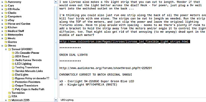
BTW - I've been working the heck out of Treepad Lite putting together notes and materials for this project. Check it out. Looks just like Windows Explorer and is a real pleasure to use. Way better than postie notes and piles of printouts. Just click the insert button to add a node to the tree. Now all I gotta do is synch up my laptop and find a place for it on the bench.

http://www.treepad.com/treepadfreeware/

Here's a screen dump to show what the interface looks like:

treepad-dump.jpg


Anyway ... try it. You'll LIKE it. They've also got a full retail version that lets you add pics and links. Mmmmmm ... links.
 
Last edited:
Wow.. very nicely organized :thmbsp:

Always liked the 9001..But from seeing some of the threads on here.. dang it looks complicated.
 
http://www.treepad.com/treepadfreeware/

Anyway ... try it. You'll LIKE it. They've also got a full retail version that lets you add pics and links. Mmmmmm ... links.

After a few minutes using this program,I like it...tnx :thmbsp:

I don't know much about QRX receivers, so I'll just watch and keep my fingers crossed

PS-I like your writing style (...but I figure the bigger they are, the bigger they blow... :D)

Wow.. very nicely organized :thmbsp:
+1
 
Wow.. very nicely organized :thmbsp:

Always liked the 9001..But from seeing some of the threads on here.. dang it looks complicated.

On the bright side ... it's WAY more complicated than it looks!

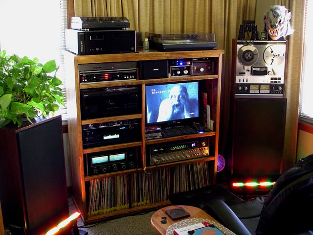
I'm fortunate in that I picked this one up BEFORE I rebuilt my "stereo" cabinet. I'd been planning on that for a while and got lucky. The 9001 measures a full 23" across. Went into the bonus round and was also able to go with a 22" monitor for my HTPC due to the width of the receiver. I also added a couple girders below the room to handle the weight and deaden the floor.

Seriously ... between that and the McIntosh MC2205 I use to drive the front channels, we're tipping the scales at about 135 pounds between those two alone. Add a couple hundred albums and various sundry odds and ends and we're talking some weight. Speakers weigh in at a pound or two also. The QRX6001 I'm currently using isn't exactly a pint size machine either, but it's got a lot of air space around it trying to fill the hole built for the bigun. Kinda hard to see in the pic, but there's solid wood separators dividing the record storage to keep the whole thing from imploding.

qrx6001-system.jpg
 
Last edited:
Benched the QRX9001 for now ...

QRX9001benched.jpg


or would that be de-benched? Till things heat up here anyway. Still a lot of questions and head scratching in my immediate future before I get in too deep.

Besides - gives me time to work on my skillz. I pulled this one off the shelf to get in a bit more practice. Way easier to work on. Not even a couple hours to get it to this point of de-construction.

qr4500-rebuild-013.jpg


Bonus points for anyone who can tell me what it is ... or at least, was.

Also got another thread going that's helping a lot. I'm almost at the point of having an inkling of an understanding of what I don't know.

Selecting Replacement Capacitors
 
Hey Skizo,

First of all the mystery receiver is a QRX3500, 4500, etc. One of those in that early series. I know, because I look 4' to the right of my computer monitor and I have a QRX6500 sitting on the bench. Your's is not a 6500 though, I can tell from the output transistors.

The whole thing about the LED's is actually pretty simple. No need to spend bucks on a supply or anything. When I do it, I build a DC supply right on the little board behind the tuning meters, with a 1n4007 and a 470uf/10v cap. That will give you about 8.4v and then you can run the LEDs in ones and twos and calculate a dropping resistor. Works great.

For the edge lighting LED's I use green ones. I have found these super bright LED's from All Electronics in LA that I really like they are very bright and you can run them at just 8-10 ma for plenty of green on the dial.

For poly caps, about the only place I think they would make any difference, over using quality audio electrolytics, like Nichicon UKW, would be on the tone control boards and maybe on the quad boards. I used to think they made a big difference, but not so much any more.

Of course the 0.1 polys would be better than the 0.047's, if you can find them small enough to fit. Just parallel them with the electrolytics in the signal path. I have gotten them from Mouser. don't know if they have the low voltage 0.1's right now, but look for them, they do carry them.

A mod I would recommend would be to add a 25v regulator for the quad board (8087,8088) boards. The supply is not regulated, and we find that almost half the quad boards that come through our shop have blown chips. I can only assume that is from high and low line AC voltage in the unit's 35 year history. I'll try to get a picture and how to do it up on my site soon.

I would also suggest reducing the gain of the power output driver boards, f2624. I reduce the gain by 9 db, and do it right where the signal comes onto the board from the preamp section. I cut a trace on the in, put a 22K across it, and replace the existiing resistor to ground with a 10k. This will reduce the noise floor by quite a bit more than 9 db by lowering the input impedance, and increase audio quality by increasing the current flow in the preamp section driving the output. Low level electronics practically always sound better when putting out higher voltage and current. If you do this gain reduction, increase the value of the input capacitor from 0.47 to 2.2uf.

I'd really think twice about the Main in/pre out mod, unless you have a specific reason. Maybe add a QBL100 remote volume and quad balance control instead. I plan to have instructions on how to do that on my site soon, also. You can figure it out from the QRX5500 schematic. The amps in the 9001 are pretty powerful, really, over 100 watts per channel, regardless of what the specs say.

And, of course, (LOL) I would recommend sending your output driver boards to me for the mod I do to the f2624 board. I add back the missing parts of the amplifier that were left out in practically all of the 70's designs, and painstakingly hand balance the currents in the the input section. This brings out inner detail and increases imaging to such a degree that anyone can hear it immediately. And there is no reduction in that Sansui warm tube like musicality.

Looks like you have a really nice 9001 to work on. NIce shop, too. Keep us posted.
 
Lots of food for thought ...
<urp! ... scuse me!>

LED LIGHTING
At this point, I'm leaning away from doing the LED lighting ... for now. Maybe somewhere down the road. I do like the soft glow of the incandescents, and as I mentioned, that's all working well for now. I've also got some notes on those LA super brights for future reference. And your power supply is easily a lot more straightforward than some of the approaches I've seen.

POLY BYPASS
Also leaning away from doing polys in the signal path. One across the rails on the main caps is definitely on the plate. I've seen what you do with the tone boards - maybe at least that. Even general purpose caps are a big improvement over what was available back in the day, and I was able to scrounge up Silmics for most of the electrolytics I'll be replacing based on the list you posted. Thanx for that. Only place I had to compromise was with the 3.3µf caps - those seem to be rare as hens teeth in audio grade. EchoWars suggested I just replace those with 4.7µf ... Hmmmmmm. Still thinking on that.

25v REGULATOR
And I'll most certainly be looking forward to some more info on that 25v regulator. A pic is worth a thousand words, but feel free to add a thousand words if you've a need to.

<tap tap tap ... are you done yet??> <G>

2624 BOARDS
About those 2624 boards - is there a trick to getting them out? I see they're a two piece edge connection, but they seemed to be fighting me when I was poking around the other day. I'm assUming they just pull out when you remove the shields. Maybe spray some D5 down into the pin holes and let them soak a bit to loosen things up? Looks like next best bet would be to remove the main cap board to give me some room to work and use a wedge of some sort to pry the connectors apart. One reason why I always rub a bit of dialectic grease on all the mating surfaces of these things. Works wonders. Worse comes to worse, I could always just desolder the connectors from the board, send them in with the boards, and let YOU get them off. <G>

I'll hold off on that hoping for a better idea. If I can get them out, I'm definitely leaning towards sending them your way for a tweak 'n twiddle.

* Darn shame Sui didn't just use the same type connectors they used on the quad boards. Those slip right out.

PRE-OUT/MAIN IN
Call me spoiled. The QR4500s certainly run rings around the x001s when it comes to IO. I always ran that to an outboard amp for the front channels and a DBX 224 switcher out of a tape loop for all the other stuff. With no POMI loop, I'm currently running a "Y" cable from a tape loop that feeds both the amp and the outboard processors on the DBX. That's working fine for now, but I expect it'd be better introducing any processing earlier in the signal, which is more or less why they do the POMI loop in the first place. I'm not worried about remote control - my listening area leaves everything eminently tweakable right from the big chair. One advantage of living in a converted cottage.

Thanx for the flowers on the shop. I like it. Could be bigger, but then I'd just have to get more junk to fill it up. And ya ... I think I got lucky with the 9001. Everything works, but it does have the telltale signs of imminent passthru failure. And as long as I'm in there ...
 
Last edited:
Just take the input connector off and then grap the board on either side and sort of wiggle and pull straight up at the same time. they come right out.

4.7uf would be fine in place of 3.3uf. Echowars really knows his stuff.

We will add polys if people want them, but frankly, once we started doing the Diff Mod, the improvement with that was so huge, it kinda made the polys seem like not even noticeable. Since it costs more to add the polys than to do the diff mod, well. . . .

And yeah, there certainly aren't many ins and outs on the back of the 9001. I tell people to make or buy a simple input select box and put it into one of the tape inputs. You can buy them at Parts Express.

And you are so right, the bigger the shop, the more stuff. I sometimes can't believe how much Sansui we have in one room. We are currently putting two (2) full 4 channel speaker systems in the shop. One for me to test with on my bench and another to listen to the rest of the time, centered on Justin's bench. That's eight speakers, plus two for the computer. And both front pairs are big speakers.

good luck. :D
 
Well ... I wiggled mightily and got nowhere ... in fact, parts of me are still wiggling ... time for a new diet. <G>

I've had luck with the D5 thing before - kinda like WD40 on a rusty nut. I got the 9001 off the shelf and figure to dab a bit over the pins, let it sit overnight and see what happens. I've got some in a small bottle that's good for that kind of stuff - just dip a pipe cleaner into it and let it dribble into the connector holes. That should break up any oxidation that could be gumming things up.

That doesn't work, there's always a torch and a five pound hammer.

You want IO, the DBX 200 is hard to beat ...

dbx200r.jpg


Can't imagine life without one. I see one BIN on fleabay right now for $69. I'm sure you could do better spinning the wheel on a bid or two. One thing you won't see is a power plug - 100% mechanical switcher.

So ... no sonic difference between running out of a pre-out/main in as opposed to a tape loop? Makes no real matter to me as long as I can use one of the two channel tape loops for that while still being able to use the 4 channel loop for my OPPO. Doesn't seem to be a problem with any of the receivers I swap in that don't have the PIMO connections.

One more vote for the 4.7µf!
 
The pipe cleaner wasn't giving me good access, so I used one of my custom red straws and the D5 can set to low to wet the sticking connectors. Let it sit a couple hours, and they popped right out.

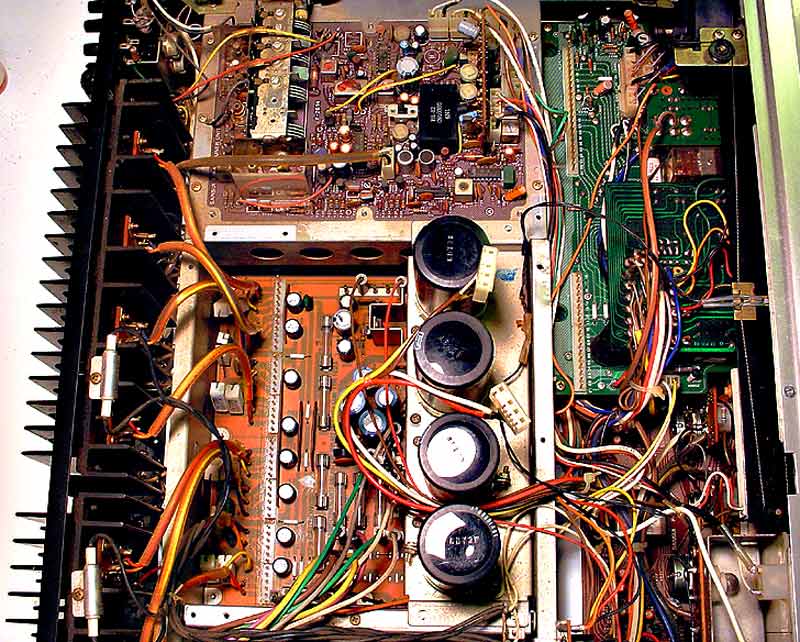
Bit more room to work now.

qrx9001-rebuild-004.jpg


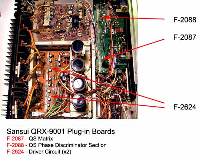
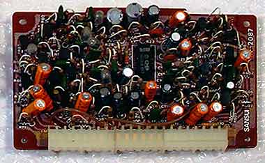
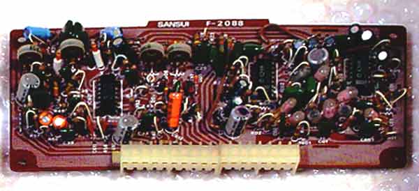
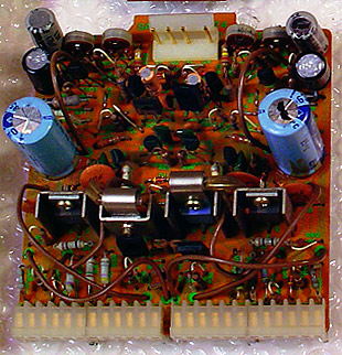
For those not familiar with the machine, here's the boards we've been talking about:

qrx9001-plugins.jpg


F-2087 (QS Matrix)

qrx9001-f2087.jpg


F-2088 (QS Phase Discriminator)

qrx9001-f2088.jpg


And the F-2624 Driver Circuit ... there's two of these:

qrx9001-f2624.jpg


When it comes to getting into tight areas, the pipe cleaners usually do the trick. Where you can't physically get in there and see what you're doing, sometimes better to use the spray. I save all my red straws and bend and stretch them as needed. Use heat shrink to bond them together, and low heat on the stove top till they just start to droop, then lay them flat till they set up. I make the bend a couple inches down as the end tends to melt, then trim to size. Works slick. I've got a few made for those "special occasions". Here's what I used this time:

qrx9001-d5straw.jpg


I will be using dialectic grease on all the pins when I put the boards back in. A little dab on a clean wiper, then rub it along the pins. Doesn't take much, but the boards should pop right out next time around.

~~~~~~~

For my next trick, I shall pull a rabbit out of my toroidal transformer. Don't laugh ... I've pulled stranger things out of equipment that's been sitting on the shelf for a while. What's the strangest you've found??
 
Old threads never die ...

Progress ...

Finished up with another receiver and back to the BIG ONE.

Stage one teardown ... Got the faceplate off ...

stage-one-teardown.jpg


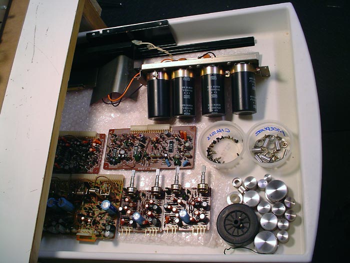
And here's my pile of modulars and parts so far ...

stage-one-boards.jpg


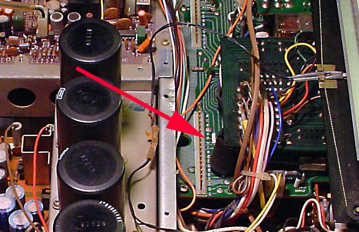
My first surprise ... once I removed the modular boards from the four channel board, what did my eye spy?

4channel-wedgie.jpg


Old school trick of applying pressure in hopes of tightening up an intermittent connection. I know ... I've done it. <G> The black round thing is an old plastic cabinet foot notched to spread the sandwich boards apart a bit. I expect it actually worked ... for a time anyway.
 
Stage Two Teardown

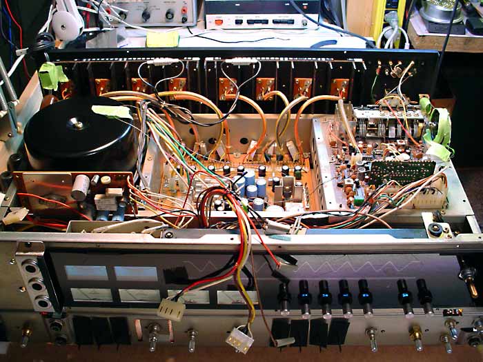
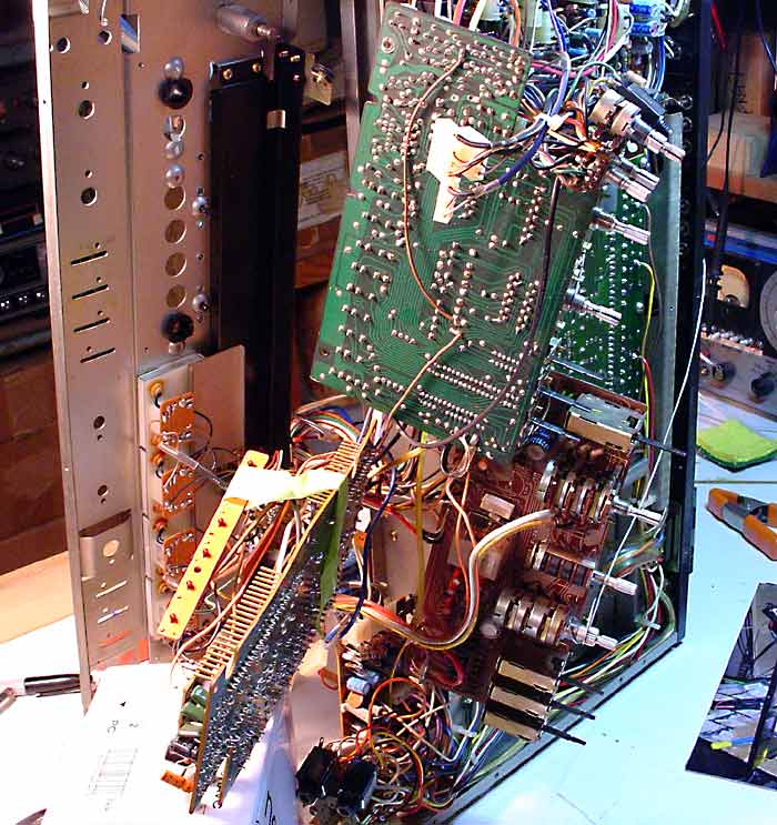
Finished removing the controls from the faceplate and moved that back out of the way. Once that was swung to the side, I removed the screws holding both primary control boards to the center rail of the chassis and was able to tie those out of the way with a couple lengths of hobby wire. You DO have to cut quite a few loom ties to allow enough slack in the remaining wires to do this. One tricky part - there's a couple strange compression clamps holding the light array for the four channel push buttons into the faceplate. Just push the center pin out towards the front with a fingernail and they pop right out releasing the board.

stage-two-teardown.jpg


As you can see, there's a whole lotta guttin' goin' on ... but ... it's beginning to look as if it's not impossible to get the job done now.

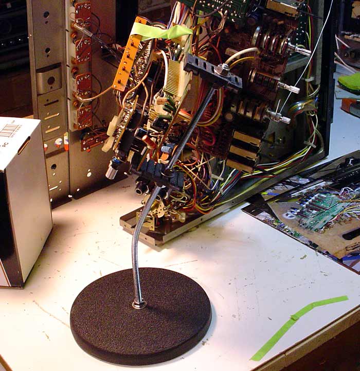
PS ... my panavise wasn't cutting it, so I made my own clamp to hold the four channel board steady. I'll be spending quite a bit of time on it, so I wanted it right. An old mike stand, some threaded stock, nuts and washers, and a couple plastic carpenter shims with a couple tweaks were just the ticket. Very sturdy and good clearance for what needs doing.

4channel-board-clamped.jpg


Enough for today - time to go listen to some music on the backup 6001 ...

.
 
Any of them good? <G>

Thanx for stopping by. I seem to remember you having some "issues" with a rebuild a bit back. Life got real interesting for a while, in a Chinese way? That thread almost convinced me to take this thing out to the graveyard and put a wooden stake thru it's beating heart. I compromised and have settled for just hanging a couple strings of garlic on the bench as I get into it.

On the bright side, I did run it thru the paces before opening it up, and everything was working, other than the intermittent stuff usually attributed to the four channel board. Last check, all channels had good output, CD4/Direct was good front and rear, SQ and QS would lose the left front and SQ would get distortion on the right also ... but "Hall" was clean front and rear, so the chips are doing their thing.

Feel free to drop some pearls of wisdom my way as I go along. Tips, tricks, condolences ... try and head me off at the pass if it looks like things are about to go horribly wrong anyway. I'm milking the board for what it's worth - if you notice in my last, there's an 8x10 glossy of a pic Xformer posted up that I used as a reference for opening it up. Hard to get a point of reference on what goes where for access at first, but it looks about the same as the pic now and I should be able to work the pinning from here. Just an amazing amount of destruction to get this far, and the fun's just starting.

So far so good I think. Next step is to desolder the daughter board. Open wide ... this won't hurt a bit!
 
Great job. I like the little stand you made to hold the 4 ch board so you can work on it. I might just have to make one of those for our shop. You're right about it being complex, but at the same time Sansui did a remarkable job of making it accessible. All the removable boards make for easy work. It's those ones behind the panel that will make a man out of you. LOL As you are finding out I'm sure.

Keep it up.

:D

And by the way, Hi Anders. Good to see you're still around. You're not hanging out too much on that Pioneer board, are you? You must have about a thousand receivers and various other gear by now, with that dream job of yours.
 
Either a man ... or a sniveling little babe crying for his mommy ... <G>

And ya ... the stand worked out way better than I expected. With the bend in the one foot 3/16" threaded rod, all I have to do is remove the board, swivel the shims around, and slap the board back in. That reverses the angle to work on the other side. Height? Just walk the nuts up and down as needed.

* EZ-SHIM is the brand name, and the grooves are already perfect to fit right over the edge of the board and hold tight without damaging them. All ya got to do is snap them off to length and drill a hole for the rod. I got a pack of 20 for $6 at my local DoIt hardware. Heck, if you can't find them, let me know and I'll send you a couple. Better yet, I'll build you a vise, call it "audiophile grade" and let you have one for $1300 (free shipping!) ...
 
Very nice, I hope you end up with a fine(er) unit! I still have to dig mine up and finish the restoration.. moving right in the middle of a recap is horrible! :S I'm going to keep an eye on this one to see if i learn a thing or to :D
 
Back
Top Bottom