• The move to the new server is done. There are some software and database maintenance updates in process. This has us passing the hat around to help out. We appreciate any donations. Seriously, even a dollar helps. The payment page may be found here - https://www.audiokarma.org/support.html

power transformer

Alfonsol

Active Member
Hi
i have a grundig 390U/S Stereo console.

the tranformer was burned because the caps in the power supply failed and someone replaced the fuse with a wire.

i no longer have the ransformer because i sended it to a technician to fix it, and he dissapeared with the transfomer, so now i have really big paperweight.

i have the schematic for the amplifier (NF2) and the voltages are here.

after rectifier and filters are 312 volts
bias -16v
heaters 2 windings of 6,3volts (1 for the amplifier 1 for the radio section)

i will try to make a transfomer.

i was unable to find the specs of the original transfomer, but my educated guess is that:

first winding 220V, 200mA (311,08 after rectifier)
second winding 12V (16,97 after rectifier) this is for bias
third winding 6,3V, 11A
fourth winding 6,3V 7A

the current rating are guesses, because i don't have information, but the fuse for the third winding is 10A and the fuse for the fourth winding is 6A.

my guess for the first winding is because the schematic says after rectifier 312V 150mA

for the current of second winding i don't have any clues , but i suppose it has to be very little current.

I am right?
anyone have the specs for this transformer?
 
Last edited:
Register to hide this ad
This is the US export version with 14 tubes, I believe - where are you located? Actual current for the heater windings is much less - add up the tube currents to get a total. Bias winding can be eliminated if you add a resistor for cathode bias (about 100 Ohm, 5 W).

Hammond 261M6 has 215V @ 269 mA, plus 6.3V @ 4A. You'd need another 6.3V transformer to handle all those tubes...
 
I am in chile.
i have an error, the voltage for the bias sfter rectifier is -16V, the have a resistor divider to achieve -11V

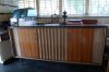
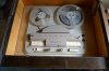
i posted some pictures.
the cabinet is in good shape, only some discoloration on the top.
the tape recorder works, and the turntable works.
 

Attachments

  • P1030017 (Large).jpg
    P1030017 (Large).jpg
    79.5 KB · Views: 33
  • P1030019 (Large).jpg
    P1030019 (Large).jpg
    64 KB · Views: 32
  • P1030020 (Large).jpg
    P1030020 (Large).jpg
    59.9 KB · Views: 28
  • P1030021 (Large).jpg
    P1030021 (Large).jpg
    54.7 KB · Views: 23
this is a long term project.
the technician dissapeared with the transformer in 1999, since then it has been collecting dust.
i also need the power tubes for one channel, because in the eartquake last year the amplifier was on my desk and 1 el84 is broken.
i found jj el84, are these good?
also i changed the seleniun rectifiers.
i also changed the filter caps.
there are lots of paper caps and they look good. should i change them?
 
Hi, nice looking console there. Cool tape deck.

Yes, change all the coupling caps. Some might be good, some bad; I find it easier to change them all while I am in there. Thankfully Grundig used values that are still available today. I use Mallory 150 series but virtually any modern coupling cap style will work. Also change out the cathode bypass caps. Ceramic tone caps may be left in place.

JJ EL84s are fine, yes.

Tom is steering you right on the power transformer - heed his advice. Even if you plan to keep the grid bias as per the schematic, you can also do that off the high voltage winding with a dropping resistor, a reversed diode, filters, etc.....you don't necessarily need a bias tap off the PT.

Let us know how you make out with it.


RWood
 
i made my homework.
the tubes in the amplifier are 4xel84 and 2*ecc83. also from this winding there is an output to the radio section that says max 0,3A ( i think this is for the dial lamps), then the total consumption for this winding is 3,94A.
the second 6,3V winding goes directly to the radio section and it says max 3A.


The hammond tranformer is a good idea, but i know a transformer factory near me( with good reputation) that can make the transformer for about the same price. if i add taxes and shipping costs, the tranformer made here is cheaper. the shipping costs to Chile usually are expensive)

i only need to say them all the specs.

i have the current for all windings but the bias.
i need to calculate a safety margin. Is there a rule of thumb for that?
 
i ordered some parts.

2 matched pairs jj el84.
i needed only 1 pair two replace the broken tube in 1 channel, but i decided two order tubes for the other channel, because i don't know how worn are the "good" tubes.

i also ordered two jj 100+100uf@500V for the filter caps.
i already replaced the filters with 4 100uf 450V caps but they fit too tight inside the chassis and i don't want any risk of shorts.
to replace the paper caps i found mallory 150 in chile, so i will use this following he recomendation of Rwood
 
i made my homework.
the tubes in the amplifier are 4xel84 and 2*ecc83. also from this winding there is an output to the radio section that says max 0,3A ( i think this is for the dial lamps), then the total consumption for this winding is 3,94A.
the second 6,3V winding goes directly to the radio section and it says max 3A.


The hammond tranformer is a good idea, but i know a transformer factory near me( with good reputation) that can make the transformer for about the same price. if i add taxes and shipping costs, the tranformer made here is cheaper. the shipping costs to Chile usually are expensive)

i only need to say them all the specs.

i have the current for all windings but the bias.
i need to calculate a safety margin. Is there a rule of thumb for that?

If you can post the schematic for the amp, we might be able to use Ohm's law to reverse engineer the current rating. I believe most bias circuits keep the current down to just a few ma, perhaps as much as 5-10 ma but if you are going to have this wound, we want to make a best effort at getting it right.

Shelly_D
 
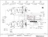
I'm sorry, but my tired old eyes cannot read this. It is just too small for me. I have circled the area in red that I need to see clearly. Is there some way of expanding or redrawing the area with the resistor values and posted voltages? That will allow us to do the calculations needed I think.

attachment.php


Thanks

Shelly_D
 

Attachments

  • NF2schematic.jpg
    NF2schematic.jpg
    85.8 KB · Views: 232
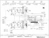
Here is the schematic for the components circled in red.
the two first caps(viewed from left to right) circled in red, are not connected to this, so i not drawed them.

The schematic i have is not good quality, but is readable on my computer. I don't know why when i upload it, it turns unreadable
 

Attachments

  • nf2supply.jpg
    nf2supply.jpg
    67.2 KB · Views: 29
i made some calculations and the current draw calculated using the equivalent of the three resistors is around 24ma.
thanks shelly_d

what curent draw i should expect from the tubes to calculate the total current draw for this winding?
 
Looking again the schematic i think i found the answer.
the current draw from the tubes should be almost 0. so maybe i will be OK with a 30mA winding?
 
This is the US export version with 14 tubes, I believe - where are you located? Actual current for the heater windings is much less - add up the tube currents to get a total. Bias winding can be eliminated if you add a resistor for cathode bias (about 100 Ohm, 5 W).

Hammond 261M6 has 215V @ 269 mA, plus 6.3V @ 4A. You'd need another 6.3V transformer to handle all those tubes...

One other way to do this, would be to get a dual-secondary 6.3v filament transformer, that would handle both the tube filament circuits. Wire all the heaters to that transformer.

Then, take the 6.3v, 4a winding on the one Tom suggested above, and use a voltage doubler on it. You will then get original bias voltage, pretty much (16v)...

Regards,
Gordon.
 
i made some calculations and the current draw calculated using the equivalent of the three resistors is around 24ma.
thanks shelly_d

what curent draw i should expect from the tubes to calculate the total current draw for this winding?

You are fine with a 24m ma. The current through the 56K ohm resistor includes the current draw for the tubes and the current draw for the bottom half of the voltage divider. Subtract the -11 volts from the -16 volts and you get 5 volts drop across the 56K resistor. Ohms law gives you 5/56k = .09 mA. The current through the 680 ohm resistor is much more dominant and keep the draw of the tubes in the range of non significant.

Shelly_D
 
Thank you.

One more question. my guess for the 220V winding is 200mA, because in the schematic says 312V 150mA at the output of the rectifier.
i don`t know if this measurement is at full power or idling.

the amplifier has 2 el84 and 1 ecc83 for each channel.
also the pre/tuner unit is powered from the amplifier( the schematic says 255V 40mA at the output to the pre/tuner) . So 40Ma of the 150mA are going to the tuner and the amplifier is taking only 110mA.

my question is 200mA is enough to this amplifier?
 
Thank you.

One more question. my guess for the 220V winding is 200mA, because in the schematic says 312V 150mA at the output of the rectifier.
i don`t know if this measurement is at full power or idling.

the amplifier has 2 el84 and 1 ecc83 for each channel.
also the pre/tuner unit is powered from the amplifier( the schematic says 255V 40mA at the output to the pre/tuner) . So 40Ma of the 150mA are going to the tuner and the amplifier is taking only 110mA.

my question is 200mA is enough to this amplifier?

The answer to that one is beyond my knowledge, sorry.

Shelly_D
 
didn't realized that in the top of schematic there is info about current and voltage on each tube.

For each el84

plate: 310V 22.5mA
anode 2,5V
g2 309V 2,5mA.

For each ecc83
anode 1: 4,4V
plate 1: 184V 1mA

anode 2: 1,2V
plate 2: 86V 0,73mA

if i add all the currents the result is: 103,46mA
The current to the pre/tuner is 40mA

Total current is: 143,46 mA
very close to 150mA, the difference may be in the current flowing in resistors to ground.

With these numbers plate dissipation is 6 or 7 watts.
so this numbers are for idling, and the amp is biased very cold.

how i can calculate peak current?
 
Another question:

jj el84 are out of stock.

they have electro-harmonix and mullard(russian reissue).
what of these 2 is better?
another suggestions?
 
Back
Top Bottom