Gregory
Soundco Kid
This is something you can do between 8:00 and 11:30 AM and that includes getting your tools and chemicals out.. and the tuner on the bench.
Getting started around 8 AM
Here we have the MR 80 on the bench. That's the reflection of the tripod in the front panel. Damn.. the camera lens is speckled!
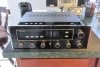
MR 80 Tuner on the bench prior to a power supply recap. A very fine instrument with proven performance.
Bench arrangement
Now the tuner is turned over and pointed to the LEFT to keep the glass from being damaged and the bottom cover removed. Being right-handed.. I always use this arrangement. Another kudo for the kitchen counter.
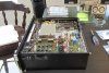
MR 80 upside-down on bench with front panel off the bench to the left. This is my standard servicing arrangement.. glass off the LEFT edge.
Removing PCB #1
The inline PCB connectors can be TIGHT! Using latex gloves like the Mrs. has, help a lot in getting a firm grip. You wouldn't pry on those plastic housings with a screwdriver.. would you?
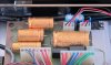
Location of Power Supply PCB #1 connectors and mounting hardware. Eight-pin inline connectors are very tight. A firm grip is needed to remove them.
Removing PCB screws
The MR 80 is built well and relatively easy to service. In removing PCB #1 fasteners, one of the tiny screws was VERY difficult to turn. Unfortunately the threads were destroyed. The good news is.. the standoff was fine after testing it with the other `clean´ screw. It may have been cross threaded during assembly? Let's not speculate. No problem really.. because I tend to replace OLD screws with stainless in the McIntosh units anyway.

4-40 x 1/4" mounting screw with threads destroyed. Luckily it came out.. and without ruining the standoff. Time to order a box of black 4-40 stainless Phillips.
Removing PCB #2
Next to remove is PCB #2. I started unhooking from the far end and worked toward the center. Most of the connectors come off easily by rocking them end-to-end. The one LONG inline was tough. It takes more force but comes off ok. There are two #4-40 board screws into standoffs, and three #6-32 bracket screws through the back panel.
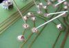
Best to inspect solder joints underneath and re-flow at least the end pads (or two) for the longer 8-pin connectors.

Power Supply PCB #2 connectors removed starting from the side wall, and working toward the eight-pin in the center of chassis.
Your tuner will look like THIS
The wire harness is tight and leaves little room. PCB #2 must be coaxed and navigated out from under with patience.

MR 80 with power supply boards removed. PCB #2 (rear) took some skill and patience to jockey from underneath the harness.
Here are the two original Power Supply boards on the bench..
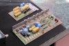
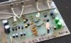
Power supply PCBs on the bench before original axial electrolytics are removed. Radial caps will be replaced when parts arrive.
and another view... I see the Light!!
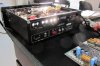
Replacing capacitors
The fun part is replacing caps! Here is PS board #1. Looks GREAT!! and what satisfaction to do the work yourself.

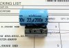
Power supply PCB #1 with new axial caps installed. These Nichicon VX series should easily be superior to the originals.
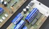
The recapped boards next to each other with six new axials installed. Also there are a couple Muse ES 10uf in the output signal path of PCB #2... and the old parts bag. Of course the radial caps will be replaced... that is after UPS arrives.

MR 80 power supply boards #1 and #2 with new axial caps.. and old parts bag. Don't forget to inspect the solder pads under the connectors!!
Summary
That's about it for today. The tuner will sit there until the second Mouser shipment arrives... probably on Monday.
Can hardly wait to get it back together and try it out.
-Greg
Getting started around 8 AM
Here we have the MR 80 on the bench. That's the reflection of the tripod in the front panel. Damn.. the camera lens is speckled!
MR 80 Tuner on the bench prior to a power supply recap. A very fine instrument with proven performance.
Bench arrangement
Now the tuner is turned over and pointed to the LEFT to keep the glass from being damaged and the bottom cover removed. Being right-handed.. I always use this arrangement. Another kudo for the kitchen counter.
MR 80 upside-down on bench with front panel off the bench to the left. This is my standard servicing arrangement.. glass off the LEFT edge.
Removing PCB #1
The inline PCB connectors can be TIGHT! Using latex gloves like the Mrs. has, help a lot in getting a firm grip. You wouldn't pry on those plastic housings with a screwdriver.. would you?
Location of Power Supply PCB #1 connectors and mounting hardware. Eight-pin inline connectors are very tight. A firm grip is needed to remove them.
Removing PCB screws
The MR 80 is built well and relatively easy to service. In removing PCB #1 fasteners, one of the tiny screws was VERY difficult to turn. Unfortunately the threads were destroyed. The good news is.. the standoff was fine after testing it with the other `clean´ screw. It may have been cross threaded during assembly? Let's not speculate. No problem really.. because I tend to replace OLD screws with stainless in the McIntosh units anyway.
4-40 x 1/4" mounting screw with threads destroyed. Luckily it came out.. and without ruining the standoff. Time to order a box of black 4-40 stainless Phillips.
Removing PCB #2
Next to remove is PCB #2. I started unhooking from the far end and worked toward the center. Most of the connectors come off easily by rocking them end-to-end. The one LONG inline was tough. It takes more force but comes off ok. There are two #4-40 board screws into standoffs, and three #6-32 bracket screws through the back panel.
Best to inspect solder joints underneath and re-flow at least the end pads (or two) for the longer 8-pin connectors.
Power Supply PCB #2 connectors removed starting from the side wall, and working toward the eight-pin in the center of chassis.
Your tuner will look like THIS
The wire harness is tight and leaves little room. PCB #2 must be coaxed and navigated out from under with patience.
MR 80 with power supply boards removed. PCB #2 (rear) took some skill and patience to jockey from underneath the harness.
Here are the two original Power Supply boards on the bench..
Power supply PCBs on the bench before original axial electrolytics are removed. Radial caps will be replaced when parts arrive.
and another view... I see the Light!!
Replacing capacitors
The fun part is replacing caps! Here is PS board #1. Looks GREAT!! and what satisfaction to do the work yourself.
Power supply PCB #1 with new axial caps installed. These Nichicon VX series should easily be superior to the originals.
The recapped boards next to each other with six new axials installed. Also there are a couple Muse ES 10uf in the output signal path of PCB #2... and the old parts bag. Of course the radial caps will be replaced... that is after UPS arrives.
MR 80 power supply boards #1 and #2 with new axial caps.. and old parts bag. Don't forget to inspect the solder pads under the connectors!!
Summary
That's about it for today. The tuner will sit there until the second Mouser shipment arrives... probably on Monday.
Can hardly wait to get it back together and try it out.
-Greg
Last edited: