Marty Socal
Active Member
Parts needed:
(Qty. 3) #276-1363 TO220 heatsinks from Radio Shack, cost $1.69 each.
http://www.radioshack.com/product/index.jsp?productId=2102856
Epoxy (I used JB Weld, slow cure).
(Qty 3) 3MM metric hex nuts from the local hardware store or the junk drawer.
Solder, 60-40 rosin core
NON-CONDUCTIVE Heat Sink Grease (NTE 303)
91% rubbing alcohol or medical alcohol pads, like they use when you get a shot at the doctors.
Optional: New transistors (Q19, Q25 = KSC2073TU qty 2) ( Q20 = KSA940TU qty 1)
Tools:
Soldering iron, Solder sucker or desoldering braid, a Drill motor with a 3/16" drill,
a phillips screwdriver and a small wrench to fit the 3mm hex nuts.
How to:
Basically what we are going to do is add the new heat sinks to the back of the old heat sinks, greatly increasing their surface area!
I found it easier to remove the three transistors and heat sinks from the board to install the added heat sinks. They usually need to be resoldered anyways, due the the extreme heat and thermal cycling these are subjected to. It might also be a good time to replace them with new transistors, if your unit has had hard usage.
Remove the transistors in the normal manner using the desoldering tool or braid, noting their positions. Separate the transistor from the original heat sink, and clean off the old thermal grease. Reapply an even thin coat of heat sink compound to the mating surfaces and resecure the transistor to the original heat sink, bend the legs of new transistors so that they fit the existing mounting holes like the old ones did. Set aside for now.
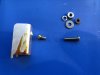
Take the new heatsinks from their packaging and prepare to drill a new hole about even with the second leg and centered so that the heat sink will have enough clearance above the wire wrapped pin and nearby comopnents once it's mounted. The original hole in the new heat sinks will make them sit too low. The size of the projection on the back of the old heat sinks that forms the threads that the transistor screw threads into sets the size of the drill bit you need to use to allow the added heat sink to get full contact with the old heat sink. IIRC, it was 3/16" (5mm). Carefully drill the new hole in the heatsinks, might help to have a vice handy to hold the part while you drill it, it's relatively soft aluminum. Once you have drilled the new heat sink so it fits over the rear projection on the old heat sink, trial fit them by installing the 3mm nut onto the excess threads on the mounting screws that stick through the old heat sink. Trial fit them into the board to make sure they clear all the other components.
Once you are satisfied with the fit, prep the parts to apply the epoxy, which helps with the heat transfer and prevents the new heat sink from falling off in service. Rubbing alcohol will remove any excess heat sink grease or fingerprints from the mating surfaces so that they stick together well. A small amount of epoxy is needed for each heat sink. The slow cure JB weld has a long setting time, but secures parts better than the 5 minute type. Mix it per the package directions and apply it to the contact area where it will fit against the old heat sink. Try to keep it off the threads of the mounting screw, then install the new heat sink and retain it with the 3mm nut. Refit them to the board and verify that they are in alignment and are not contacting the other componenets. Set them aside overnight for the epoxy to cure. Once you are satisfied they are cured, you can solder the transistors back onto the board.
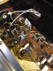
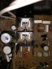
Here's a view of the heat sinks installed. Notice the nut that helps secure the new heat sink to the old, and that it's set with enough height to clear the nearby components:

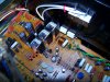
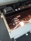
A closeup of the other side, showing the retaining nut and clearances to the components on that side. It is not touching the wire wrapped pin, it clears it by maybe an 1/8" or so.

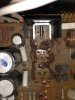
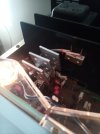
You can see the dark grey JB Weld epoxy where the two heat sinks are glued to each other:

Overhead view with a better shot showing the nuts, make sure they are tight!

Results:
The maximum temperature I measured with a lazer aimed infra red temp gun on the transistors before the heat sinks were added was about 180*f after the radio was in operation for 1/2 hour.
After installing the added heat sinks, the max temp was measured at 125*f. Quite a difference!
Hope you guys find this useful!
(Qty. 3) #276-1363 TO220 heatsinks from Radio Shack, cost $1.69 each.
http://www.radioshack.com/product/index.jsp?productId=2102856
Epoxy (I used JB Weld, slow cure).
(Qty 3) 3MM metric hex nuts from the local hardware store or the junk drawer.
Solder, 60-40 rosin core
NON-CONDUCTIVE Heat Sink Grease (NTE 303)
91% rubbing alcohol or medical alcohol pads, like they use when you get a shot at the doctors.
Optional: New transistors (Q19, Q25 = KSC2073TU qty 2) ( Q20 = KSA940TU qty 1)
Tools:
Soldering iron, Solder sucker or desoldering braid, a Drill motor with a 3/16" drill,
a phillips screwdriver and a small wrench to fit the 3mm hex nuts.
How to:
Basically what we are going to do is add the new heat sinks to the back of the old heat sinks, greatly increasing their surface area!
I found it easier to remove the three transistors and heat sinks from the board to install the added heat sinks. They usually need to be resoldered anyways, due the the extreme heat and thermal cycling these are subjected to. It might also be a good time to replace them with new transistors, if your unit has had hard usage.
Remove the transistors in the normal manner using the desoldering tool or braid, noting their positions. Separate the transistor from the original heat sink, and clean off the old thermal grease. Reapply an even thin coat of heat sink compound to the mating surfaces and resecure the transistor to the original heat sink, bend the legs of new transistors so that they fit the existing mounting holes like the old ones did. Set aside for now.
Take the new heatsinks from their packaging and prepare to drill a new hole about even with the second leg and centered so that the heat sink will have enough clearance above the wire wrapped pin and nearby comopnents once it's mounted. The original hole in the new heat sinks will make them sit too low. The size of the projection on the back of the old heat sinks that forms the threads that the transistor screw threads into sets the size of the drill bit you need to use to allow the added heat sink to get full contact with the old heat sink. IIRC, it was 3/16" (5mm). Carefully drill the new hole in the heatsinks, might help to have a vice handy to hold the part while you drill it, it's relatively soft aluminum. Once you have drilled the new heat sink so it fits over the rear projection on the old heat sink, trial fit them by installing the 3mm nut onto the excess threads on the mounting screws that stick through the old heat sink. Trial fit them into the board to make sure they clear all the other components.
Once you are satisfied with the fit, prep the parts to apply the epoxy, which helps with the heat transfer and prevents the new heat sink from falling off in service. Rubbing alcohol will remove any excess heat sink grease or fingerprints from the mating surfaces so that they stick together well. A small amount of epoxy is needed for each heat sink. The slow cure JB weld has a long setting time, but secures parts better than the 5 minute type. Mix it per the package directions and apply it to the contact area where it will fit against the old heat sink. Try to keep it off the threads of the mounting screw, then install the new heat sink and retain it with the 3mm nut. Refit them to the board and verify that they are in alignment and are not contacting the other componenets. Set them aside overnight for the epoxy to cure. Once you are satisfied they are cured, you can solder the transistors back onto the board.
Here's a view of the heat sinks installed. Notice the nut that helps secure the new heat sink to the old, and that it's set with enough height to clear the nearby components:
A closeup of the other side, showing the retaining nut and clearances to the components on that side. It is not touching the wire wrapped pin, it clears it by maybe an 1/8" or so.
You can see the dark grey JB Weld epoxy where the two heat sinks are glued to each other:
Overhead view with a better shot showing the nuts, make sure they are tight!
Results:
The maximum temperature I measured with a lazer aimed infra red temp gun on the transistors before the heat sinks were added was about 180*f after the radio was in operation for 1/2 hour.
After installing the added heat sinks, the max temp was measured at 125*f. Quite a difference!
Hope you guys find this useful!


 ). I just used a longer screw that threads in nicely in the old heatsink and a nut to hold the new heatsink onto the old one and thermal grease. I only used it on the transistor that powers the tuner and some other circuitry. That is the one nearest the large heatsink and the hottest. I feel comfortable enough with the other two to be left alone. But I agree, it wouldn't hurt to do the two others. Adding the heatsink does make a huge difference.
 ).
). .
.