• The move to the new server is done. There are some software and database maintenance updates in process. This has us passing the hat around to help out. We appreciate any donations. Seriously, even a dollar helps. The payment page may be found here - https://www.audiokarma.org/support.html

Sonic Transformation of a Vintage Toshiba/Aurex Preamp

Leestereo

Super Member
I have a Toshiba SY-335 (same as Aurex SY-330/335) preamplifier which is a good candidate for modifications/upgrades since it has a relatively simple signal path that uses op-amps as active devices. I had previously successfully upgraded the phono stage, see http://www.audiokarma.org/forums/showthread.php?t=494228 for details. As with the phono stage upgrade, it was not just a "part for part replacement", but along with the the use of modern parts (e.g., low ESR capacitors, stacked film capacitors, metal film resistors, "soft recovery" diodes), the circuit was examined to see where simple improvements could be made without modifying the pcb (e.g., increasing or decreasing capacitance of capacitors, elimination of capacitors where possible, op-amp replacement).


Part I: Power Supply

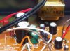
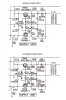
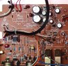
The power supply provides a regulated output of +14 V and -14V for the phono and line stage as well as the 20V needed by the muting stage. The resistors were replaced with same value metal film types. The original diodes were replaced with UF4005, ultra fast, "soft recovery" types. The "soft recovery" property of these diodes generates less noise and hence there is less potential noise to be amplified by the circuits. They also cost the same as regular diodes; their use won't hurt and will likely contribute to better sound. Surprisingly, the original main capacitors (C42 and C43) are listed as 470µF/25V in the schematic, but were actually 1000µF rated at 16V; the problem is that the rectified secondary voltage is 20V!

Generally, if appropriate to the circuit, and there is sufficient space on the board, replacement capacitors will have higher capacitance and sometimes increased voltage (especially if the original voltage rating is just marginally higher than actual voltage). If the function of the capacitor is only DC filtering, or decoupling, then increasing the capacitance 2X-3X for small caps is usually not an issue (also keep in mind that caps in vintage equipment were often rated at -10%, +50%). In this particular regulated power supply, capacitors C42, C43 are just filtering the DC, and the replacements were Panasonic FM 2700µF 25V low ESR capacitors (~3X the capacity of the originals). Similarly, C36, C37, C40 and C41 were replaced with low ESR with about twice the original capacity. Capacitors C38 and C39 are on the base of the regulator/pass transistor and were kept at the original value of 100µF to maintain the speed of he regulator circuit, note that they can be increased, but not to the same extent as the other caps (my understanding that if increased beyond 330µF the "tightness" of the regulation will be adversely affected).

Part II will detail the line stage upgrade...
 

Attachments

  • SY-335 closeup.jpg
    SY-335 closeup.jpg
    115.5 KB · Views: 361
  • SY-335 PS.jpg
    SY-335 PS.jpg
    114.5 KB · Views: 328
  • SY-335 POWER SUPPLY red.jpg
    SY-335 POWER SUPPLY red.jpg
    111 KB · Views: 315
Register to hide this ad
Part II: Line Stage

The line stage uses the JRC4558 op amp; this op amp is very common in Japanese designs from the early 80s on and was even common in the mid-90s. Despite its ubiquity, it is not considered a particularly good op-amp for audio. Looking at its datasheet, none of its specs are particularly good and its slew rate (1V/µs) limits its open loop bandwidth to 15kHz. After looking at too many op amp datasheets, I found that choosing an op amps by looking at their datasheets is difficult since many op amp datasheets only provide a partial picture of the device, often lacking are the distortion specs and even noise specs. Also, choosing the appropriate op amp is also made difficult by the fact that there are very few test comparisons of op amps available.

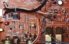
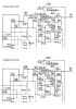
The op amps I had initially short listed for this project were the NJM2068, NJM4580, NJM4560, NE5532 and the OPA 2134 since these should be drop-in replacements without any changes to the circuit. Luckily, I did find on-line a relatively recent test comparison of 3 of these op amps here: http://nwavguy.blogspot.ca/2011/08/op-amp-measurements.html In the %THD and bandwidth tests the NJM2068, NE5532 and the OPA 2134 were all essentially the same. Interestingly, in the noise measurements, the NJM2068 was the best; it bettered the NE5532 and the OPA2134 in noise by 3dB and 6dB, respectively. In the end, I used the NJM2068DD op amp (the second "D" denotes a selected low noise version) for the line stage. As I have previously posted, for the phono stage upgrade, I had chosen the NJM4580DD to replace the NJM4558 since it was quieter in a RIAA circuit than the NJM2068, 0.8µVrms vs. 1.4µVrms (in a line stage the NJM4580 is noiser than the NJM2068 by about 3dB). Other changes I made included replacing the ceramic by-pass cap (C56) with a larger (0.1µF) film cap. Also, the ceramic cap (C57) in the low pass filter was replaced with a polypropylene one to reduce distortion; I also decreased the value from 270pF to 100pF to essentially eliminate any high frequency phase shift. The output electrolytic cap was replaced with a same value stacked film capacitor. And lastly, all 5% carbon film resistors were replaced with equivalent 1% metal film types.

This was a relatively simple project that was also very cost effective, with about $25.00 in parts. One of the objectives of this project was to maximize the sound potential of this particular design by using parts that weren't available in 1980 (e.g., low ESR caps, soft recovery diodes, better op amps), or were considered too costly for a mid-range commercial product by the bean-counters (e.g., metal film resistors).

How does it sound?
The modification/upgrade really transformed an average sounding preamp to an excellent sounding unit. It sounds quite similar to my Hafler DH-110 now, very clear and neutral; also with the lowered noise floor, I seem to be hearing all of the low level sound details more clearly. I think that the largest gains in sound quality were the result of the increased capacity in the power supply and the op amp change. All other changes helped too, but I think in a more subtle way.

Whenever I modify/upgrade a piece of equipment, I try to remain skeptical of any sound improvement I perceive and I usually ask others to audition the mod (I don't tell them what I think or what the mod is supposed to do) to try to gain some objectivity. In this case I had Bktheking borrow the preamp and use it with his system(s). His feedback was positive, and maybe he'll add his comments to this thread.
 

Attachments

  • SY-335 line closeup.jpg
    SY-335 line closeup.jpg
    97.9 KB · Views: 273
  • SY-335 line RED.jpg
    SY-335 line RED.jpg
    116.7 KB · Views: 268
Last edited:
Unbelievable! This is the kind of info I was looking few days ago. I post at the Yamaha forum:

Link: http://audiokarma.org/forums/showthread.php?t=504375 (from post #2)

The only thing is that the opamp in question is a 9-pin NJM4558S opamp (IC101) and, since those Brown Dog SIL to SIP are only in 8 pins configurations, choices to me are pretty limited here in the Netherlands...

Having decide to put some fresh new caps trying to transform this weak unit in a more vivid and faster one (power caps will be replaced with multiple in-parallel ones), I'd like to see if it worths also upgade the IC101 (NJM4558S) on this unit...
 
standing on the shoulders of giants

Hi

I have been upgrading a SY 355 inline with your thoughts and very useful suggestions. The only difference was the use of a LM4562 in the line stage, which has made a significant difference, as has the power supply upgrades.

I am about half way through, try substitution(s), check with scope and voltage meters...and then connect to an amp (upgraded NAD2200) and hear (or not) the impact.

a very educational process that I am thoroughly enjoying...:)

thanks Leestereo for doing the ground work!
 
Glad to be of service.

Regarding the LM4562, did you have to install additional decoupling capacitors near if?
 
Excellent walk-through of the upgrade process. If I had free time my Carver C4000 would be under the knife in a heartbeat. Now I'm going to be dreaming about opamp mods - so much for "sleep".

As for inductor's comment - whatever dude. If you've never had the urge to improve a piece of gear by using measurably better components then that's your choice. Just don't pretend we're all wired the same way. Respect our differences or STFU.
 
Last edited:
Interesting, I have one of these preamps, and wouldn't mind some upgrades.

Would there be any benefit in just replacing the op-amps, and not touching the other components?

Charles.
 
IMO, it would be better to start with the power supply capacitors and the signal path capacitors in this particular preamplifier.
 
I agree. Replace beat up caps first. Solder in some sockets for the op amps at the same time but leave the originals in there. Get used to the way it sounds with the new caps and then start playing around.
Worst comes to worst and you've got a freshly capped unit with stock op amps.
 
Good to see you enjoy yourself; that's what matters. :yes:

Some thoughts back for your consideration.

1) PSU

In pre-amps, it's all about keeping noise levels as low as possible. Starting with the mains input, a standard C8 IEC mains filter block (chassis mounted on the back, to which you connect to mains power cable) is key of keeping mains noise out of the unit before it gets in. Filtering the mains at chassis limit (i.e. no mains cable/wires running through the unit before being filtered) is key. Until being filtered/bypassed, the mains wires act like an antenna inside a noise sensitive unit. low-cost improvement would be to solder a 0.1uF~0.47uF so-called X2 capacitor (X2 means certified to be across mains terminal without protection, mandatory type when you put a bypass cap across mains like that; X2 will be clearly printed on it, and can be recovered from any PC power supply).

Often you'll see a 0.1 uF film cap (mylar/polyester will do) directly across the secondary of the transformer as well (shorting any HF which comes through the transformer, or being picked up by the transformer). When missing, I often solder one at the pins where the transformer wires arrive on the PCB.

Regarding upsizing the snubber caps across the diodes, be aware that larger value caps also do allow more HF coupling across the diodes (from Tx to DC circuit). Hence, larger values won't necessary help. And because this is a low-current unit, not much nasty diode behaviour can be expected (I would go back to initial value)

Recommended to add 0.1~0.22uF film caps across C36/C37 (MKP or MKT, 50 V rated) to short out any HF picked up or generated by the regulator circuit. (zeners are noisy, that's why C38/39 exist in the first place). High end units often have a second film cap across C38/39, but IMO it's more efficient to put them across the final PSU output caps C36/C37 to bypass whatever HF noise may come out of the PSU section.

I agree with the value upgrade of the electrolytics, though my usual choice is Nichicon KG/KZ/FG.

TR05 and TR06 should not be underestimated as noise generators, specially when they are not properly cooled. If too hot (i.e. over body temp, improve their heat sinks)

When the PSU PCB is separate from the pre-amp PCB, then 0.1 uF decouple caps should be placed at strategic places (requires PCB layout analysis).

2) Line stage

Why did you delete coupling capacitor C19 (this is actually a DC-blocking capacitor!) ? Be aware that any DC level will now be fed to the opamp and cause a permanent DC current (i.e. DC offset) to flow through the opamp, heating it up unnecessary (and reducing it's lifespan, and very possibly increasing the noise levels).

Better put a 4.7~10 uF MKP film then nothing ! Nothing wrong with a Nichicon FG electrolytic (but keep rated voltage as low as possible).

C17/R27 are not in use when you don't use loudness

C57 is a HF roll off / bypass capacitor. Lowering it to 100pF means that that you double the frequency bandwidth to the opamp. Could be good or bad.... probably better signal wise, but with less noise decoupling.... trade-off case....

Also key to low noise opamp performance is that the +/- 14V power rails are decently decoupled as close as possible to the opamp legs. Opamp text books all stress on double capacitors to cover large bandwidth decoupling, i.e. an 4.7/10 uF electrolytic (or better: tantalum) + 0.1 uF ceramic cap. Personally I would use a NP0 (C0G) ceramic + 10 uF tantalum (adding the latter on the PCB solder side across C56)

When you're really looking for the best possible upgrade, then replace C23/25/29/31 by polypropylene (MKP) 50V caps (e.g. Panasonic ECQP or equivalent).

Duly deoxit the volume pot.

Well, enjoy.
 
Last edited:
I'm curious as to how feasible it is to install a bypass switch for the phono input, which would allow me to use an external phono preamp instead of the built-in one. I have a nice tube phono stage that I'd like to continue using, and there aren't quite enough inputs for all the sources in my rack as it is...

Charles.
 
How big a deal is it if I leave the C44 and C45 caps at their stock values? Forgot those suckers in my digikey order, and it's not really worth the shipping charge to order them alone...

Charles.
 
To answer my questions, leaving C44 and C45 stock seems to have no detrimental effect. I'll swap these in later. And yes it is completely feasible to bypass the phono preamp. I found the place on the board where the phono stage enters the switch, and I cut the traces and wired in a switch so that I can have the onboard (and upgraded) phono stage enabled, or bypass it entirely so I can use my tube phono stage.

And now I'm debating on swapping out that selector switch with one that has a few more positions! It would be nice to do away with my switchbox and have all my inputs selected via the preamp. Hmm...

Also, I changed the red LED for blue, and drilled three small holes behind the volume knob and added blue LEDs there, so I can see the volume control in the dark now. It adds a nice glow around the knob, aided by the reflections from the chrome trim. This preamp is SUPER easy to modify! Hmm++.... I could probably add a NR loop too.... but that may be a little ambitious. :D

Charles.
 
I just completed some more mods, this time to an SY-665. I never, ever use the front microphone input... so I removed the circuit board, removed the pot from the board, and added a stereo headphone jack. Wired it to the pot and now I have a front panel stereo input for an iPod or whatnot. Was a pretty simple modification too! Ideally I'd like to replace that pot with a DPDT rotary switch, or a pushbutton, but I have to find something that will work and look nice in the chassis. (Black plastic buttons don't cut it, and a DPDT rotary switch of the right size and shape is unobtainium it seems)

Still, I'm quite happy with the mod so far. I just don't need to "mix" the inputs, so I'd prefer a switch.

Charles.
 
Interesting, I was hoping to do the same mods on my SY-665 that I followed on this page for the 335... but low and behold, the SY665 has a completely different design.

In the phono stage/input side of the motherboard there are two TA7322P op-amps (for left and right channels, as it appears these are mono op-amps), as well as two K117s and one C2088 transistor for each channel.

On the other side of the main board, I'm seeing one pair of 2SC1626 + 2SA816 transistors over by the power supply section. Since there is only one pair, I'm guessing these have nothing to do with the input signal. There's no manual or schematic on HiFiEngine for this model, and I'm not good at following a circuit board and figuring out how it all works. (I'm more of a "follow detailed instructions" kind of guy).

I don't know much about those TA7322P op-amps, are they any good? I'm going to replace all the capacitors in there, and I'm curious if there are better op-amps to drop in place. Thoughts?

Charles.
 
Sorry to dig this old thread out again but I did today the update of a second SY335 and it was again a total transformation.

The first was a little over half a year ago on a Toshiba SY335 now running in my main system. With every step it got better and better. The biggest step was changing the OP amps. I only had a set of NE5532 on hand but wow did it change the sound and imaging.
The second update was done today on an Aurex version SY335 Mark II. I'm not sure what the changes between Mk I and Mk II are since there are no obvious circuitry or value differences but also here it did a huge step up. On this I went the full way including not only all lytic caps but also the ones in the feed back loops of the line stage and phono circuit with MKT's and ooh boy it's good. Also here I used the NE5532, I had them available.

Over all, I can only recommend to follow the changes and see or hear for yourself!
 
I'm using that 665 in my office system (paired with a SC-655 amp). I liked the front-panel-input mod on my SY-665 so much that I duplicated it in the SY-335 in my main system. I went back to the 665 and replaced the pot with a rotary switch. I like that marginally better than having the pot in there... but can't really notice any difference in sound. If I could find a nice push button with a similar diameter aluminum button, I'd likely install that in both preamps. The convenience of a front-panel input is HUGE. Next step, I think I might pull signal feed before the op-amps and route them to line out/line in for an equalizer loop. (Or in my case, an auto-correlator loop, for noise reduction).

Charles.
 
Back
Top Bottom