• The move to the new server is done. There are some software and database maintenance updates in process. This has us passing the hat around to help out. We appreciate any donations. Seriously, even a dollar helps. The payment page may be found here - https://www.audiokarma.org/support.html

TD124 motor rebuild step by step

Lapslah

Super Member
A little background - I bought my TD124 at a church rummage sale in about 2000. You don't want to know what I paid. :D I got it home, cleaned it and lubed it, and it has served me well for about 14 years with no trouble. Replaced the arm and cart, made a new armboard - regular stuff. It has always taken about a full side (20 minutes, give or take) to settle in at full speed. I'm told this is normal, and is even referenced in the manual. I always spin it by hand before starting it up because I figure anything I can do to reduce the stress on a 50 year old motor is wise. It has always been silent in the room - until you drop the needle. Then there is a motor hum that is clearly being picked up by through the needle and transferred to the output. It's not horrible, and only noticeable on quiet passages with the volume cranked up. But the motor still has the original rivets, so I figure it's time...

There have been many write-ups on similar rebuilds - some of them very good. In fact, I used them myself for reference. But I have seen others ask for detailed step-by-step instructions, so that's what I'm going to attempt to do here. I'll probably get TOO detailed for many. Also be forewarned - I claim no special expertise. Like many of us here, I'm just the guy who tried it, and here's how it went...

I started by measuring just how bad the noise was by cranking up my amp and using the dB meter on my phone (which is admittedly not calibrated and reads high, but it's all I had) while the needle was traversing the silent tracks on a test record. The motor noise coming through the speakers peaked at 67dB on the scale. I'm pushing about 775 watts/channel through 4 Ohms. I hope to recreate the same conditions when I'm done to see if there's a measurable difference (God, I hope so).

So here's my starting point:
 

Attachments

  • 106_1721.jpg
    106_1721.jpg
    70.3 KB · Views: 113
  • 106_1722.jpg
    106_1722.jpg
    66.7 KB · Views: 96
  • 106_1723.jpg
    106_1723.jpg
    58 KB · Views: 84
  • 106_1724.jpg
    106_1724.jpg
    73.9 KB · Views: 88
  • 106_1726.jpg
    106_1726.jpg
    78.2 KB · Views: 101
  • 106_1728.jpg
    106_1728.jpg
    64.7 KB · Views: 104
Register to hide this ad
After removing the platter and armboard, I emptied the oil from the well and removed the well. It had a very slight leak so I will be replacing the gasket, which is original and has a small tear between the outer and inner sections. I cleaned the well and set it in a paper cup full of oil to soak. I then took pictures of the wiring so I'd be sure to put everything back the way it belonged. However, I later found that I could rebuild the motor without disconnecting the wiring. I include the wiring pic here for anyone who chooses to do it "right" instead of the easy, cheating way I chose. Following that is a picture of the way the screws and washers were on the motor, as I was taking it apart. With the cover off, you can see the condition of the housing and armature after 50 years.
 

Attachments

  • 106_1734.jpg
    106_1734.jpg
    79.1 KB · Views: 158
  • 106_1733.jpg
    106_1733.jpg
    76.4 KB · Views: 143
  • 106_1732.jpg
    106_1732.jpg
    88 KB · Views: 134
  • 106_1731.jpg
    106_1731.jpg
    75.8 KB · Views: 145
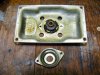
After drilling out the rivets (which is very simple if you've ever used a drill before - no worries), you can now see the condition of the felt washers which will be replaced. I bought Jim Campbell's kit from that auction site. It came with the washers already oil-soaked and ready to go in, plus new bushings, bolts, washers, and nuts to replace the drilled out rivets, and a properly sized drill bit. It makes the job much simpler.

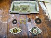
Now the really overly detailed stuff. Following are pictures of each piece being removed and placed from left to right as they come out, in sequence:
 

Attachments

  • 106_1739.jpg
    106_1739.jpg
    132.8 KB · Views: 95
  • 106_1738.jpg
    106_1738.jpg
    126.3 KB · Views: 91
  • 106_1737.jpg
    106_1737.jpg
    133.9 KB · Views: 89
  • 106_1736.jpg
    106_1736.jpg
    106.6 KB · Views: 105
  • 106_1735.jpg
    106_1735.jpg
    107.9 KB · Views: 120
  • 106_1740.jpg
    106_1740.jpg
    131.2 KB · Views: 111
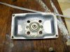
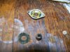
I then cleaned the cover with brake cleaner and began the reassembly of the bottom. Here I made an error that can be seen in the pictures - I attached the bottom cover where the thrust plate and tiny ball bearing (also both included in Jim's kit) fit before I had reassembled the rest. This must go on AFTER the felt washers are installed because the top and bottom diamond-shaped plates must be screwed on together (DOH!). No big deal - I just unscrewed it. Also note that the ball bearing should not be left on the thrust plate as it is in the picture - it should be stuck on the bottom of the motor shaft with a small dab of grease (I used white lithium grease) so it ends up in the right place. So reassembly looks like this, minus the caveats mentioned above. Note that, with Jim's kit, the X-shaped metal piece must be cleaned and re-used. The last, out of focus picture is the ball bearing stuck to the shaft with white lithium grease.
 

Attachments

  • 106_1746.jpg
    106_1746.jpg
    91.4 KB · Views: 98
  • 106_1745.jpg
    106_1745.jpg
    104.7 KB · Views: 87
  • 106_1744.jpg
    106_1744.jpg
    114.6 KB · Views: 76
  • 106_1743.jpg
    106_1743.jpg
    109.8 KB · Views: 81
  • 106_1742.jpg
    106_1742.jpg
    98.4 KB · Views: 88
  • 106_1747.jpg
    106_1747.jpg
    57.5 KB · Views: 116
Now for the top. It is essentially the same as the bottom except that the motor shaft passes all the way through and goes to the pulley. If you don't want to disconnect the wiring, you'll have to do a little twisting and turning to get to everything, but it's really not bad. You'll note that my felt pads on the top were in much worse shape than the bottom ones - dried out and hard.
 

Attachments

  • 106_1752.jpg
    106_1752.jpg
    72.8 KB · Views: 64
  • 106_1751.jpg
    106_1751.jpg
    115.3 KB · Views: 60
  • 106_1750.jpg
    106_1750.jpg
    70.9 KB · Views: 62
  • 106_1749.jpg
    106_1749.jpg
    122.5 KB · Views: 60
  • 106_1748.jpg
    106_1748.jpg
    94.6 KB · Views: 69
Reassembly:
 

Attachments

  • 106_1753.jpg
    106_1753.jpg
    130.2 KB · Views: 68
  • 106_1755.jpg
    106_1755.jpg
    73.5 KB · Views: 57
  • 106_1756.jpg
    106_1756.jpg
    127.9 KB · Views: 56
  • 106_1757.jpg
    106_1757.jpg
    109.4 KB · Views: 74
So the motor is now finished - refer to disassembly pics for reassembly of motor housing. My present hang-up is a cracked mirror for the strobe. I hope to find a replacement and finish up this afternoon.
 
Well, I couldn't wait on a mirror so I put it back together without. The old mirror has lost its reflective backing and someone had previously installed another on top of it, and the second one was cracked. I put the original back in, but can't see a darn thing on it. Oh well - temporary until I can source a new one.

But here's the big news - got it all put back together and ran the same noise test with the same settings, and went from 67dB before to 38 dB after! :banana: That's WAYYY better than I expected. I'm a happy camper. :thmbsp:
 

Attachments

  • 106_1759.jpg
    106_1759.jpg
    44.2 KB · Views: 51
does it come up to speed immediately now?

No mirror = No idea! :scratch2: LOL

One unexpected result though, is this - even though the hum was not noticeable except on rare occasions with high volume and quiet musical passages, it seems to me that the constant drone was acting like a resonance effect on the mechanism of stylus/cartridge/arm. Now that it's gone, everything seems clearer and more defined, like the whole thing is working more efficiently.
 
I found a replacement mirror in a ladies' makeup compact. I could have sworn I wrote it down in a post here but I'm having trouble locating it. Will dig and let you know.

Nice work on the motor. The only thing I didn't see you mention was the adjustment after assembly. Basically you assemble the motor and tighten until finger tight, then run it a while, put a stethoscope on it (or just listen) and tap it with a screwdriver handle or something similar, focusing on the areas around the rivets, so that the bearings seat in alignment. Very easy and makes a noticeable difference in noise.
 
Someone asked me a while ago, when I had my 124, to measure the mirror. FYI, for those who want to make one, they're 2 3/16" X 1 1/4" and fairly thin.
 
Thanks for the note on adjustment, jgordon. I did not know about that procedure. I wonder if it's too late for me?

As for the mirror, I tried using a mirror from one of my wife's old compacts, but it needed to be cut down and was very brittle, so it ended up in pieces. Yesterday I picked up a 5-pack of small mirrors at a local craft store. I'm hoping that I'll get it right in 5 tries... Any advice on cutting down a mirror would be appreciated! Now that the table is put back together and set up, the dimensions will be helpful - thanks Gary.
 
Well, that didn't last long. As I mentioned, I replaced the gasket on the bottom of the oil bath holding the spindle. I used a cheap piece of sheet plastic as recommended... somewhere in someone's how-to thread. It's leaking. Any recommendations of what to use for a good seal?
 
Back
Top Bottom