Many of you have been following the once again 'incredible' work of Dave Gillespie on his little Magnavox 8604-00 'Flea' amp. If you haven't, and want an interesting, informative, educational, and entertaining 'read'..... go seek out the 'Magnavox Flea Power' thread of Dave's. But, be warned: If you're like me, you'll probably want to go out and build one of these for yourself.....which is just what I'm 'trying' to do.
So here I am in this thread rather closing the barn door after the horse has left. Why? Well, my amp is 'built'.....but not right yet. I have some trouble-shooting yet to do, as I've got a 'nasty' noise problem; not your typical 'hum' issues I've had in the past. In fact, the amp is DEAD QUIET!! My amp has a rather aggressive 'scratching' kind of noise. Much like an arcing across a tube socket or something similar. At low volumes...VERY low.....it doesn't act up at all. But, turn the vc just a little and you start to hear the noise on the dynamic and bass passages. Turn it up more and it's distorting all over. VERY annoying, not to mention disappointing! This clearly points out the difference in 'repair-refurbish' vs 'scratch build'. Were this once a 'working' amp, I'd be relatively sure that I was looking for a failed component. However, as a 'scratch' build..... I've not got to go back and see if I followed the road map (schematic) correctly. To that end, I 'think' I've gone over it enough to verify my build IS to Dave's diagram. However, I'm also not so presumptuous as to believe I could not still have made an error. So, in posting the following pics, if anyone sees anything suspect, PLEASE let me know.
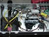
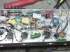
The amp started as just a generic version of a little SE EL84 amp. I'm not sure what it came out of, but I confirmed it did have 4 ohm output transformers. Also, it's Power Transformer was a bit more 'gutzy' than that of the original Magnavox in Dave's project. My HV is a bit higher than that of the Maggie....so in a post on Dave's thread he suggested I simply add another stage to the PS filter section to bring my B+ into range. In my pics you'll see a black axial 33uf - 350V cap and a 470 ohm -5Watt resistor. This is that section. My B+ now sits at 270V AFTER the second stage vs the 265 Dave has on his Schematic (found on Pg 7 Post #103 of Dave's thread). My B+1 is 250 vs 245. So..... Onward.........
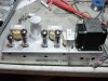
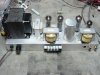
I pulled the 4 ohm OTs off and replaced them with the one's Dave suggested from AES. Got them mounted, along with a Dynaco choke I had on hand. Specs between the suggested Hammond show it at 1.5H at 56 ohms, 200ma and 400 volts vs the Dynaco choke at 1.75H at 62 ohms, 200ma and 400 V. So, as Dave stated to I believe Derek in his thread: OK to use that choke. Where I think I may have a problem is in my multi-cap. I had to scrounge the parts boxes to come up with something suitable. I found a 3-section cap that was 40-40-40 at 400, 350, 300. The Maggie (and Dave) use a 3-section of 40-40-20 at 350, 350, 300. While mine 'should' be useable, I note that it has a slight bulge in it.....and I'm REALLY skeptical of it's quality. Further, the noise I hear is one I've heard in the past in amps with failed PS filter caps. So..... I'm hangin' my hat on that, and buying a replacement tonight. (would have done it over the weekend by AES-CEDist was closed for the 4th).
If you look at my pics, you'll see a couple places where I had to get creative with some resistors in order to come up with the proper value. ie, I didn't have the 820 cathode resistors of the 2 sides of the 12AX7. So, in combining a 470, 330, and two 10 ohm resistors..... I got my 820 ohms. Is that a problem? I hope not! If so, please let me know. Likewise I had to pair up a couple more resistors to get a proper value....but again, it got me to the correct level vs taking a 'close enough' approach. My only other deviance is the use of a 390pf cap on the bypass of the feedback resistor vs Dave's spec of 300. Could this be my problem? Maybe! I'll get a 300 and 'fix' that issue. But, my inclination is that my problem lies in either A) that PS issue. or B) something I simply did wrong!
So, here are my pics! I will update this after I get the multi-cap and remaining other passive parts and 'correct' the 'make do' stuff. With luck I'll have the multi-cap from CE by the weekend. The passive parts will either come from CE or a local supply place on the North side of Baltimore about a hour away. To conclude, I'm COMPLETELY open to ANY comments; good, bad, or indifferent. And, if anyone sees any kind of problems with my build, PLEASE let me know!! I can't tell you how frustrated with myself I was when I flipped the switch, heard this dead quiet amp...and then got that noise problem. It was like going from 'success' to 'failure' in a span of 2 minutes!! Onward.........
Tom D.