• The move to the new server is done. There are some software and database maintenance updates in process. This has us passing the hat around to help out. We appreciate any donations. Seriously, even a dollar helps. The payment page may be found here - https://www.audiokarma.org/support.html

DG-SE1 Build 4: 5V rectifier version

Wharfcreek

Jack of all trades, master of none!!
Staff member
Moderator
Subscriber
Well, the beat goes on! This build was a 'proto-type' for a 5 volt rectifier version. I know DerekVa used a 5V rectifier in his..... and after giving the matter some further consideration, I decided that prior to my 'final' build, I need to do a mule version myself. So, this was that.

In all honesty, I 'thought' I was doing pretty good with this amp. Started with the 5AR4 rectifier.....and after finishing the build in relatively short order, I got the voltages all within Dave's spec....... and hooked up the test speakers. Sounded good on those....so went to the Cornwalls. At that point I started hearing some hum....and actually lost a channel. Long story short, the loss of channel was in the driver tube socket...... just dirty. BUT.... this noise problem revealed that I also had no 'separation' between channels. Amp was acting like dual-channel 'mono' amp...where input from either channel drove both channels equally. Quick Shout-Out to Gadget and Dave for finding my failure to connect my speaker 'negative' connections to chassis ground. And, 'rookie' error on my part. Fortunately, quick and easy fix.

After running amp for several hours I noted that my PT was getting REALLY hot! Unlike Dave's 'original' DG-SE1, in my builds I've been using a 4-stage power supply filter system. This in order to 'adjust' the B+ voltage between stage 1 and 2....with stage 1 being a cap off the rectifier and the choke. Choke feeding second stage cap. Then, an 'adjustable' bridge resistor between stage 2 and 3...which allows me to set Stage 3 at the specified 265 volts. Then the 820 resistor between stages 3 and 4. Anyway, I had a 500 ohm resistor in my 'adjustment' stage when using the 5AR4. I tried a 5Y3 and was able to drop the resistor to 130 ohms.....or 370 LESS ohms of resistance in the PS. I'm not sure the filament draw of the 5Y3 has any advantage over the 5AR4....but I 'might' have reduced the heat in the PT by a smidgeon. It's still hot....too hot for my liking....but after several hours of straight running......it's still alive. So....for now, I'm living with it.

Amp is built WITH the associated Bias Adjust Pots....and REALLY sounds good! This may be psychological.....but I think getting this amp at EVERY detail of the specs provided DOES improve it's performance. However, my very first build still impresses me...and I've yet to add the bias pots to it.

Anyway....my 'Final' build of this amp will be with the Transcendar 7W OT, and with a Hammond 270EX PT. The Hammond PT is rated at 144ma of DC current capability...with a 3A rectifier filament section, and a 4A filament section for the output and driver tubes. Maybe 'overkill'....but this one will NOT overheat!! Also using the new Dynakitparts C-354 choke, with a bit more inductance (1.75 vs 1.5 of the Hammond) and being 'shielded'...which is something I couldn't find on any of the Hammond units. But, more on that build when it begins. Parts are all ordered....2 to 3 weeks to get the OTs from Transcendar. Thread will begin then. For now, regarding build 4, I'm going to quote DerekVa here....and say it's time to stick a fork in it and call it 'done'........

Thanks for looking! BTW, note the neat label atop the chassis for the Bias adj level!! label maker: Flea Mkt find - $1 WC
 

Attachments

  • DG-SE1 Build 4 001.jpg
    DG-SE1 Build 4 001.jpg
    75.8 KB · Views: 71
  • DG-SE1 Build 4 002.jpg
    DG-SE1 Build 4 002.jpg
    76.5 KB · Views: 57
  • DG-SE1 Build 4 003.jpg
    DG-SE1 Build 4 003.jpg
    76.2 KB · Views: 56
  • DG-SE1 Build 4 004.jpg
    DG-SE1 Build 4 004.jpg
    80.4 KB · Views: 52
  • DG-SE1 Build 4 005.jpg
    DG-SE1 Build 4 005.jpg
    66.3 KB · Views: 68
Register to hide this ad
Glad to hear its sounding good. All chassis should be like that one. Plenty of holes to mount stuff. :thmbsp:
 
Religious chassis (holy) are definitely an advantage. In this one's case, the extra air flow is REALLY needed!! WC
 
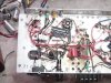
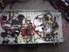
Here are a few shots under the skirt. WC
 

Attachments

  • DG-SE1-4 006.jpg
    DG-SE1-4 006.jpg
    110.3 KB · Views: 47
  • DG-SE1-4 005.jpg
    DG-SE1-4 005.jpg
    99.9 KB · Views: 37
  • DG-SE1-4 004.jpg
    DG-SE1-4 004.jpg
    125.8 KB · Views: 41
  • DG-SE1-4 003.jpg
    DG-SE1-4 003.jpg
    118.6 KB · Views: 38
  • DG-SE1-4 002.jpg
    DG-SE1-4 002.jpg
    115 KB · Views: 48
Tom -- To reduce peak current draw from the transformer's HV winding, reverse your filter circuit order, and loose one of the filter caps. The amp will still be plenty quiet.

Come off the rectifier tube with only an appropriate resistor, which goes to the first filter cap and choke, the choke goes to the second filter cap and OPTs, and on to the 820 ohm resistor. Adjust the resistor off the rectifier tube to give you 265 volts to the OPTs.

The required resistance will be less than the 500 ohms you are using now after the choke. By inserting the resistance between the rectifier and first filter cap, the peak current draw from the HV winding will be reduced, which will result in lowering the transformer temp.

Nice build!

Dave
 
Hey Dave,

I actually got rid of the 500 ohm resistor when I went to the 5Y3 rectifier. Even with the 5Y3, I still need 130 ohms off of the choke to get to 265 at the next stage. I might add that the multi-cap has a 60 uf section in it..... and I was wondering if that was also part of my problem. I don't know enough about PS design to decide just which section to toss out. I have the 33uf axial (450V) in there now as the first section. Then to the first of the 3-sections of the multi-cap at 40uf @450V, then the 60 uf at 450V (where the OTs are currently connected and where I'm right dead-nutz on 265VDC) , then the final section is 40uf @ 350V. I ran out of 820 ohm resistors, so I have a 1K in there now.....and instead of 255 I think I'm at about 258...... close enough!!

Given the first axial cap is 'new'..... should I try your format and eliminate the 60 uf section and put the OTs on the first 40uf of the can cap? Or, should I keep that 60uf section just for the added reserve at the OTs? Then just use one of the 40s.....like the one 450V section? I've not measured the filament voltage as per Gadget's suggestion...but he mentioned the Current Inrush Limiter as an idea too.

BTW...thanks for the 'nice build' comment....but this was really more of a 'tossed together' effort. Sounds damn good though! Funny how that works. She may be ugly, but she sure can cook!!..........lol

WC
 
Last edited:
You can tie the extra 33 uF to the OPT tap if you want, but you won't need it. Come off the rectifier with an R to 60 uF/Choke to 40 uF(OPT tap) to 820 ohm-40 uF.

Dave
 
Got it! Thanks Dave. I'll perform those changes today. Tom
 
Dave, Changes made. Associated removal of the one stage also resulted in my being able to drop the former 130 ohm resistor down to 50 ohms..... so, another 80 ohms of resistance out of the PS. I noted a bit of a 'bubble' in the 'vent' area of the 350V \40uf section of the multi-cap......so I decided to just eliminate that one and I used that 33uf axial for the last section. Now going from the rectifier with the 50 ohm resistor to the choke \ 60uf section of the multi-cap. Then out of the choke to the other 40uf multi cap section and the OTs, and using a 1K \ 5 watt to join to the screens \ driver. I'm awaiting arrival of the 820 ohm resistors....but for now, the 1K is giving me 255 V at the screens \ drivers....and my B+ is running at 268. I suppose I need a 60 ohm resistor.....but I'm back to the 'run what ya brung' stage. Anyway, it's hooked to speakers now.....and bias is dialed in at 5.83. I'm right at the edge of my 50 ohm pots......and seem to be either at about 5.74V....and as I move off the end to the wiper, it drops to this 5.83V. I suppose I could replace the 120 ohm resistors with 100 ohm resistor...which would then put the pot about amid-ship. But, it also may be weak tubes. So, just going to run it 'as-is' for a while and see how it pans out. HOPEFULLY...the power transformer will be notably cooler. I will say, I'm just listening to it now in dead silence....and I LIKE that!! And, I think this provides good info for those who wish to attempt this after me.

Dave, thanks for the advice and counsel!

Tom
 
Well, amp has been running for about 45 minutes now....just 'on'....not playing music. The PT is still hot.....if it's any cooler than it was before I did all this, I can't really tell. I can wrap my hand on it....but it's border line making me remove it immediately for fear of being burned. I have to say if it dropped by a few degrees.......it didn't drop enough to make me feel 'comfortable' about it. So, I think this amp is destine for a new PT, or to just run 'hot' forever. As it sounds so good, I don't think it will be a candidate for the auction block. But, as hot as this PT gets.....I don't see this as being a viable candidate for someone else to own. Guess I'll have to go looking for another PT. Oh well........... WC
 
Have you got a surface thermometer or IR Laser thermometer? The hand usually makes for a rather poor judge as to absolute determination of "safe" transformer operating temperature. Hot water in the home is typically 120 F, while "normal" operating temps for a transformer can easily be 140-150 F. A transformer is actually "hot" at 175 F, with 200 F being the limit of safe operation.

Dave
 
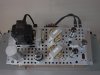
Dave, I have to chuckle! I just returned from some errands.....left the amp 'on' for about 5 hours now.......maybe 6. PT is pretty damn hot....but as you say; the hand is not the best judge. NOT having a good surface thermometer or an IR laser thermometer, I decided to 'improvise'. The little glass container was just received at a wedding being full of 'mints'. I liked it....so brought it home. I've now filled it with water, and I'll see just how hot the water gets after an hour or so using the Meat Thermometer as a gauge. Will this system work? Who knows......... But, it's perhaps a bit more scientific than the 'hand' program. Anyway..... if 200 F is an upper limit......I sincerely doubt it's that hot....so maybe I'm OK. But, we'll see. I'd love to see the thing in the 160 to 165 range......even 175. I'll give an update later. If the water boils........ I'll drop in an egg! lol WC
 

Attachments

  • Tranny Temp setup 001.jpg
    Tranny Temp setup 001.jpg
    65.9 KB · Views: 19
Well.....guess I got a lesson in 'hot' as well. The 'meat thermometer' in the water bottle trick didn't seem to be going anywhere. After nearly 2.5 hours, I hadn't seen the needle move any to where I thought it was even working. Also, I remembered I'd purchased a couple of the HFT 'advanced' multi-meters....which come with the contact thermometer probe that Dave mentioned. I knew I'd kept one of those probes......so I got it out, put a fresh battery into the meter, and set the probe UNDER the water bottle. After a few minutes I read 53 degrees centigrade, or only 127 degrees Fahrenheit. Now, 10 minutes later....still at 53. Looks like I pushed the 'Panic Button' WAY too early! However....good info again. I wasn't aware of the temps Dave mentioned......and I guess at 127.....my 'hand' is overly sensitive! Nice to know I've got that temp probe thing too. Glad to have put it to some legitimate use.

WC
 
SOV, no options with a 'buck' winding. Wish there was.....but now looks like it's just doing what it's supposed to do. And....well within 'normal' limits if the 140 to 150 is the mid-point. At 127.....guess I'm sitting pretty!! Damn...just seems 'hot' though! Another lesson learned! And, it now makes ALL my other amps running their PTs on the 'cool' side....good to know as well. WC
 
Yea, I was just curious. I've seen this a couple of times and wondered if doing that could cause PT overheating. I run a very large outboard bucker for all my tube gear. (what little I have!) I suppose a temp gun should be on my list of things to get as well.

One thing's for sure, you have a thing for these amps!
 
Tom -- It would be better to use place the sensor on the transformer, a small piece of insulation over the sensor, and then use some electrical tape over that to attach it to the transformer -- this to make sure that the bowl of water wasn't acting as a heat sink.....

Dave
 
Hey....wait until you see version 5!! Hopefully the OTs and PT will arrive within the next couple weeks. After that, I'm diverting my attention to 'selling' stuff....including several amps I have.....and then 'buying' a set of high-end full-range speakers. Something small and as efficient as I can get. I have to say, that 'listening' experience with this little amp and those Cain & Cain speakers was like an epiphany. Hearing that cello play through those things was perhaps one of the most 'realistic' sonic reproduction experiences I've ever had. Simply put: they were amazing! But, the 'flea' amp held it's own against the big-gun 300B...which is also amazing! So, I need to get me a set of those!!!......or something comparable! Any suggestions would be appreciated. WC
 
Dave,

Did as you suggested....now reading 60 degrees C (140F). The meat thermometer never hit the 140 F mark.....which is where it basically starts indicating meat temps. The water was definitely NOT as hot as the PT, so that program was probably a bust. But, this thermometer probe would seem to be pretty reliable, and confirm that at least the PT is not in the danger zone. Once again....3 hours of work for nuthin!!....but a good lesson learned! I probably could have left it alone with the 5AR4 in it.....but I'm glad to have the 5Y3 in there....and I DID find that the one section of the multi-cap was 'perhaps' starting to shoot craps. AND..... I'm down to only 50 ohms of resistance in the power supply!! So, a lot of 'good' came out of the exercise! Not all for naught! Thanks to all for the help!! Tom D.
 
Back
Top Bottom