

chicagozer
Active Member
I wanted to say thank you to everyone who's been posting technical info on this forum. I mostly lurk while I'm trying to learn as much as I can, but the information here has been invaluable.
Due in no small part to help I've gotten directly and indirectly here, I've managed to bring this Radio Craftsmen 500 amp back from the dead.

Aside from two dead chokes and a dead power transformer, this is what I started with underneath.

The resistors didn't test anywhere near spec and not trusting old caps, I decided to go ahead and haul out the passive components. Knowing my limited soldering skills, I was cringing at the point to point wiring so I decided to use a turret board instead.
I was hoping that it won't introduce any newfound interference. Worst case, I could just start again the old way.
A couple dozen hours later, everything wired up, checked and rechecked and ready for launch.

Started up on the variac; no smoke, go to 100% and it (surprisingly) started playing on the first try. Very nice feeling indeed.
The sound was very nice; just the faintest of hiss out of the speaker with no input. Couple days of goofing with it. No observable change and figure for a 60 year old amp I can live with a hiss I can't hear from a foot a away.
Anyway, this morning I was noodling with it again, and discovered I had not wired the negative feedback correctly and shunted it out. So got that resolved, and whoa that fixed the hiss. Dead silent.
So on to my questions. The circuit uses a LCLC circuit in the rectifier stage. Big choke on this guy, but because there is no leading capacitor the DC voltage doesn't get the normal bump. The 550-0-550 power transformer was cooked and the biggest replacement I could find was 500-0-500.
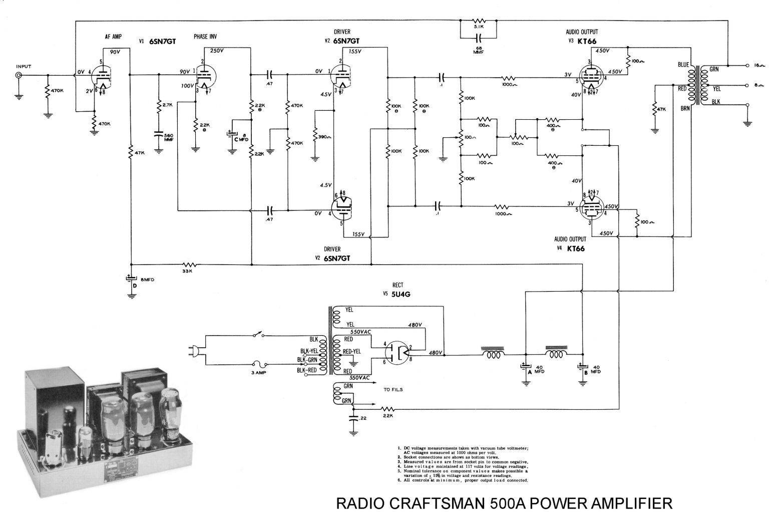
So my tube voltages are a bit underspeced. I was goofing around with the Duncan PSU II software and it appears I can add a small capacitor in front of the first choke to get the necessary bump in the voltage. I tried a .560uf cap but I think it may have been too much because the balance pot started smoking
Thankfully, it didn't seem to cook anything else once I removed the leading cap. Should I try a smaller cap here? I was wondering if it's safe to test the B+ voltages with only the rectifier tube installed? I tested with the power tubes out but wanted to know if it was save to run the rectifier with the 6SN7s removed until I can confirm the voltages.
Also, the negative feedback 5.1k/680pf really did the trick on the limited amount of hiss I was hearing. But it cut the gain noticeably. Is there a way to "lessen" the impact? Or should I not bother about this and just inch up the preamp volume?
If you got this far, thanks for reading")
Jim
Due in no small part to help I've gotten directly and indirectly here, I've managed to bring this Radio Craftsmen 500 amp back from the dead.

Aside from two dead chokes and a dead power transformer, this is what I started with underneath.

The resistors didn't test anywhere near spec and not trusting old caps, I decided to go ahead and haul out the passive components. Knowing my limited soldering skills, I was cringing at the point to point wiring so I decided to use a turret board instead.
I was hoping that it won't introduce any newfound interference. Worst case, I could just start again the old way.
A couple dozen hours later, everything wired up, checked and rechecked and ready for launch.

Started up on the variac; no smoke, go to 100% and it (surprisingly) started playing on the first try. Very nice feeling indeed.
The sound was very nice; just the faintest of hiss out of the speaker with no input. Couple days of goofing with it. No observable change and figure for a 60 year old amp I can live with a hiss I can't hear from a foot a away.
Anyway, this morning I was noodling with it again, and discovered I had not wired the negative feedback correctly and shunted it out. So got that resolved, and whoa that fixed the hiss. Dead silent.
So on to my questions. The circuit uses a LCLC circuit in the rectifier stage. Big choke on this guy, but because there is no leading capacitor the DC voltage doesn't get the normal bump. The 550-0-550 power transformer was cooked and the biggest replacement I could find was 500-0-500.

So my tube voltages are a bit underspeced. I was goofing around with the Duncan PSU II software and it appears I can add a small capacitor in front of the first choke to get the necessary bump in the voltage. I tried a .560uf cap but I think it may have been too much because the balance pot started smoking
Thankfully, it didn't seem to cook anything else once I removed the leading cap. Should I try a smaller cap here? I was wondering if it's safe to test the B+ voltages with only the rectifier tube installed? I tested with the power tubes out but wanted to know if it was save to run the rectifier with the 6SN7s removed until I can confirm the voltages.
Also, the negative feedback 5.1k/680pf really did the trick on the limited amount of hiss I was hearing. But it cut the gain noticeably. Is there a way to "lessen" the impact? Or should I not bother about this and just inch up the preamp volume?
If you got this far, thanks for reading
Jim