Caveat:
I've built a lot of tube amps and other gear, completely rebuilt several solid state amps, and repaired about 10 solid state amps, a whole bunch of preamps, and other gear over the years, but I'm not an EE or a professional. However, I've rebuilt 5 GFA 555 II models and a 585 LE, and have spent a lot of time working on these amps. Hopefully someone else will come up with good ideas as well, since I haven't seen this problem before.
More questions:
1. Have you checked bias?
2. Have you checked DC offset? I previously said the op amp DC servo would not likely be a failure item, but if something else is amiss, it could be trying to handle large amounts of DC offset, which would likely originate on the input board (more below).
3. Does it immediately show this failure mode when started from cold?
4. Have you tried any cold spray on any of the input board components?
If it were me, I'd focus on the input board and the power supply first. I would not suspect the output transistors, but more likely something on the input board, and to a smaller extent, the bypass caps on the output modules, but I doubt that. It could also be the main filter caps perhaps - did you have the means to test them? They are usually good, but not always! The interaction between having L and R channels connected makes me suspect either something in the main power supply, or perhaps the VAS section on the input board. I also doubt it is the drivers on the output modules, but you could carefully desolder the legs from the posts and check - they are easy to access if the modules are unbolted.
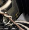
In fact, your photo shows the typical board scorching caused by the VAS transistors getting too hot, They should be elevated higher on their leads, and the current approach is to fit them with good heat sinks.
That mica crust is interesting - haven't seen that before. They are dry caps, not polarized, no electrolyte, so it looks like some other form of electrolysis has occurred, potentially from the adjacent electrolytic cap if it has leaked into the board, or perhaps the high heat of the adjacent transistor has caused some reaction with the mica cap. Sometimes people spill liquid into the amp through the slots, but I think you'd not see this crust on just the single leg of that mica cap - it would be spread around.
It is best with these boards, if you are trying to keep them, to replace all electrolytic caps, and install new VAS transistors, elevated up more from the board, and with good heat sinks. You might want to replace all of the input board transistors with new substitutes, but if you intend to replace the differential pair because they don't test good or very close to each other, you should buy matched pairs from someone (see below).
If the caps have leaked to the board, something that was more common with the 565 and 585 than this model, you may not be able to ever clean the board properly, particularly if it has suffered the kind of heat damage yours has. The electrolyte seeps through the board fibers to other parts of the circuit and causes many issues (though not typically the pulsing volume you note).
A great resource for replacement boards, if you choose to go that route, is Chris Hoppe - hoppesbrain.com. You can also read his blog posts and look at his detailed photos to get more helpful info. I've used several of his input boards and 2 power supplies and they are excellent. They can transform this into a truly excellent sounding amplifier that compete with my Mark Levinson, Sony TAN-ES80, Nakamichi PA7II, and other higher-quality vintage amps I have.
Last comment: I haven't seen those output transistors on any Adcom GFA 555 or 555 II before. I wonder if they were replaced by someone else at some time in the past.
Here's one I just rebuilt using one of Chris' new power supplies, some really big filter caps, and a new input board. The performance is several steps above the stock amplifier and sounds truly excellent. You may not want to spend the cash to go this far, so just focus on the likely cause of the type of problem you are noticing.
View attachment 2783076


")

")
