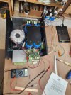
Starting a new thread on the B&K Ref 2220 to share info.
Looking for more power and, specifically, more current to drive my speakers, I've recently acquired a B&K Reference 2220 for a good price, from a Goodwill in the Midwest.
For those unfamiliar, this amp is rated at 350 W/ch into 4 ohms and can supply 75 A of output current (for comparison the Class D amps using the TI TPA3255 can supply somewhere around 25 A). It is a pretty simple Class AB design, with 5 pairs of 2SK1058 MOSFETs forming the output stage. There is no active protection circuitry, but the rails are fused and the signal is not DC-coupled.
Prior to connecting it to anything valuable I checked the DC offset, which is low (<20 mV) on both channels. It sounds great to my ears, with great bass and great bass control.
After discussion with another AKer, who shall remain blameless, I noticed a barely audible hum at idle. Both channels. Audible with my ear 6" from the speakers and not otherwise. No inputs, no change with input shorted or open. No change with changes in preamp output volume (no source). Hi ho, hi ho, off to the bench we go...
DC rails are all at or about 70 VDC. The AC ripple measured across the cap terminals (15000 uF and the size of soda cans, qty 4) is around 260 mV. This is less than 0.5% of the rail voltage and, per ChatGPT, 'excellent' for a power amp power supply. So my tentative conclusion is that the PS is mostly working properly and I don't need to replace the filter caps.
After unscrewing the PS board from the filter cap screw terminals, I measured 0 V and ~7 V, respectively, of residual voltage across the caps on each channel. So either one side is leaking or one side is more effective at discharging the caps than the other.
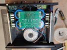
The transformer is 650 VA and 5 1/4" in diameter. Eg large. The amp emits a significant magnetic field, enough to induce a major hum into the system if I sit my preamp (Adcom 715) on top of it. So either / both companies didn't shield their stuff well enough. Pass the mu metal sheets. That or something else is broken which I don't understand yet. The sit at a distance now.
There is only about 15 mV of AC output voltage on the speaker terminals at idle. Hard to believe that's audible, but there it is. The hum is not induced into the speaker cables as it does not change when the cables are moved around, but I may try this test again. The transformer has some mechanical hum but it is tight in the chassis.
I can feel heat coming off the driver boards and heat sinks when the amp is at idle. Not alot, but more than I remember from other amps, in my limited experience.
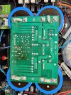
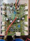
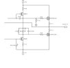
The PS board is B&K part number 10611, Rev C in this case. This board is shared across a couple of B&K amps and populated differently, depending. On this board there are 2 bridge rectifiers. On the recent ST-1400M thread by user @Stoddrob found here, there is only a single bridge rectifier. So the one B&K schematic available should apply to this amp, at least in part.
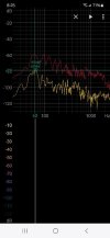
Next step is to connect an oscilloscope and measure the frequency, or reconnect the amp to the speakers and do an FFT of the sound, if possible. Maybe move the speaker cables around more.
After that I may try to measure the bias current via the fuse holders. Adjusting the bias requires some mechanical disassembly, unfortunately.
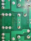
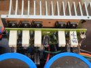
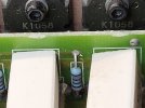
Some pics attached FYA. Note the initials on the 5 W MOSFET source resistor. Either someone has been in here prior or this is like (hand-built) Aston Martin engines, back in the day, having nameplates identifying the guy who built them, allowing A-M owners to further engage in pecker contests.
Tim
Looking for more power and, specifically, more current to drive my speakers, I've recently acquired a B&K Reference 2220 for a good price, from a Goodwill in the Midwest.
For those unfamiliar, this amp is rated at 350 W/ch into 4 ohms and can supply 75 A of output current (for comparison the Class D amps using the TI TPA3255 can supply somewhere around 25 A). It is a pretty simple Class AB design, with 5 pairs of 2SK1058 MOSFETs forming the output stage. There is no active protection circuitry, but the rails are fused and the signal is not DC-coupled.
Prior to connecting it to anything valuable I checked the DC offset, which is low (<20 mV) on both channels. It sounds great to my ears, with great bass and great bass control.
After discussion with another AKer, who shall remain blameless, I noticed a barely audible hum at idle. Both channels. Audible with my ear 6" from the speakers and not otherwise. No inputs, no change with input shorted or open. No change with changes in preamp output volume (no source). Hi ho, hi ho, off to the bench we go...
DC rails are all at or about 70 VDC. The AC ripple measured across the cap terminals (15000 uF and the size of soda cans, qty 4) is around 260 mV. This is less than 0.5% of the rail voltage and, per ChatGPT, 'excellent' for a power amp power supply. So my tentative conclusion is that the PS is mostly working properly and I don't need to replace the filter caps.
After unscrewing the PS board from the filter cap screw terminals, I measured 0 V and ~7 V, respectively, of residual voltage across the caps on each channel. So either one side is leaking or one side is more effective at discharging the caps than the other.
The transformer is 650 VA and 5 1/4" in diameter. Eg large. The amp emits a significant magnetic field, enough to induce a major hum into the system if I sit my preamp (Adcom 715) on top of it. So either / both companies didn't shield their stuff well enough. Pass the mu metal sheets. That or something else is broken which I don't understand yet. The sit at a distance now.
There is only about 15 mV of AC output voltage on the speaker terminals at idle. Hard to believe that's audible, but there it is. The hum is not induced into the speaker cables as it does not change when the cables are moved around, but I may try this test again. The transformer has some mechanical hum but it is tight in the chassis.
I can feel heat coming off the driver boards and heat sinks when the amp is at idle. Not alot, but more than I remember from other amps, in my limited experience.
The PS board is B&K part number 10611, Rev C in this case. This board is shared across a couple of B&K amps and populated differently, depending. On this board there are 2 bridge rectifiers. On the recent ST-1400M thread by user @Stoddrob found here, there is only a single bridge rectifier. So the one B&K schematic available should apply to this amp, at least in part.
Next step is to connect an oscilloscope and measure the frequency, or reconnect the amp to the speakers and do an FFT of the sound, if possible. Maybe move the speaker cables around more.
After that I may try to measure the bias current via the fuse holders. Adjusting the bias requires some mechanical disassembly, unfortunately.
Some pics attached FYA. Note the initials on the 5 W MOSFET source resistor. Either someone has been in here prior or this is like (hand-built) Aston Martin engines, back in the day, having nameplates identifying the guy who built them, allowing A-M owners to further engage in pecker contests.
Tim