• The move to the new server is done. There are some software and database maintenance updates in process. This has us passing the hat around to help out. We appreciate any donations. Seriously, even a dollar helps. The payment page may be found here - https://www.audiokarma.org/support.html

Building a Rod Elliot ESP-P3A Amplifier

OK, where to start?

The transformer has two secondaries (4 leads total not including primaries). Each secondary pair is connected to the AC leads of a bridge rectifier. There are 2 rectifiers, one for each rail polarity (+ or -).
One rectifier output goes to either the positive or negative capacitor lead depending on which side the rectifier it's on. The other rectifier output lead goes to a copper strip ground between the two capacitor banks.
The - (minus or black) speaker lead comes back to the same capacitor grounding strip per Rod's instructions. The grounding strip is then connected directly to the grounding lug of the IEC socket. There is another chassis ground that can be seen in the lower left of the case back in the model image above. This is the 'star' ground, all the grounds from the circuit boards go there. It is also connected to the IEC socket ground. There is no daisy chaining and I hear no hum.

Hope this is clear.
I went with Antek
http://www.antekinc.com/transformers/
 
Last edited:
OK, where to start?
The transformer has two secondaries (4 leads total not including primaries). Each secondary pair is connected to the AC leads of a bridge rectifier. There are 2 rectifiers, one for each rail polarity (+ or -).
One rectifier output goes to either the positive or negative capacitor lead depending on which side the rectifier it's on. The other rectifier output lead goes to a copper strip ground between the two capacitor banks.
The - (minus or black) speaker lead comes back to the same capacitor grounding strip per Rod's instructions. The grounding strip is then connected directly to the grounding lug of the IEC socket. There is another chassis ground that can be seen in the lower left of the case back in the model image above. This is the 'star' ground, all the grounds from the circuit boards go there. It is also connected to the IEC socket ground. There is no daisy chaining and I hear no hum.

Hope this is clear.

Thanks, yes, this is helpful.

I'm going to order his circuit board. I'm glad the instructions are clear on grounds. Restoring old pieces is easier: Just don't change ground wiring. Building from scratch requires knowing the difference between signal and chassis ground... which I will learn.

Do the recommended outputs: MJL4281A/MJL4302A require electrical insulation (looks like you have them in there)? I have no experience working with TO-264 packages and want to know if I should order insulators as well.

Oh, and what VA rating did you choose for the transformer?
 
MJL4281A/MJL4302A require electrical insulation
Yes

fgh-60n60-fgh60n60-igbt-transistor-con-diodo-D_NQ_NP_881815-MLA29817787164_042019-Q.jpg
 
Last edited:
I built the P3A and absolutely loved it. I generally don't listen to music loud but it was so clean sounding I kept turning it up. I had just finished it and was enjoying listening to it while working on another project when a bare wire from the other project landed on the open P3A board and let the magic smoke out. When I recover emotionally I'll build another.
 
I built the P3A and absolutely loved it. I generally don't listen to music loud but it was so clean sounding I kept turning it up. I had just finished it and was enjoying listening to it while working on another project when a bare wire from the other project landed on the open P3A board and let the magic smoke out. When I recover emotionally I'll build another.
I hate it when that happens..:D
 
Sorry for so banal a question: any guidance on the various spade connectors (for power) and the pin connectors for the audio/in out?
Attempts to find them on Mouser swim in infinity w/o the right keyword.
 
It looks like I may not get to build another.

It has been a month and a half since he mailed it and when I contacted him to see about what happens if it doesn't show up I basically got "I mailed it, it's out of my hands. There is no tracking." as a reply.

I've ordered things that cost a couple of dollars from China or Eastern Europe and gotten tracking on the shipment so this is disappointing with $70 in pcbs.
 
It looks like I may not get to build another.

It has been a month and a half since he mailed it and when I contacted him to see about what happens if it doesn't show up I basically got "I mailed it, it's out of my hands. There is no tracking." as a reply.

I've ordered things that cost a couple of dollars from China or Eastern Europe and gotten tracking on the shipment so this is disappointing with $70 in pcbs.
Hopefully it will eventually show up.
 
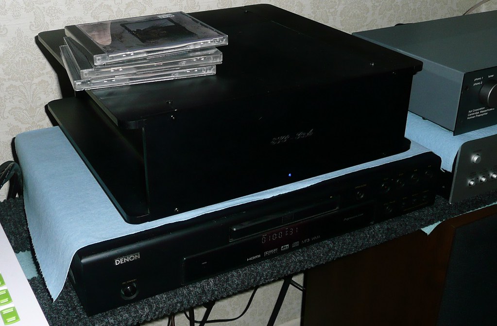
Here's the finished amp putting hours in on the test rig, driving a pair of Polk Monitor 10's quite loud!

46137094645_15520a32b3_b.jpg


46326957264_a501e86be3_b.jpg
Glad you said that's your 'test rig'. Hope your final setup has your speakers at least 6' apart and your components not sitting on top of them lol. . If those are your final or keeper speakers. rebuilding the crossovers in Monitor 10's is worth it and easy. Can't really hear or sense all your amp work after burn in using a old ancient pair of speakers with old crossovers..
 
Sorry for another horribly banal question. The holes for the electrolytics measure at 4mm center to center and stock sizes for caps are 3.5 and 5 mm.
What did you chose?

Edit...sorry I see my caliper is out of wack on the inside measurement points. It's 3.5. Sorry for the noise.
 
Last edited:
Back
Top Bottom