
• The move to the new server is done. There are some software and database maintenance updates in process. This has us passing the hat around to help out. We appreciate any donations. Seriously, even a dollar helps. The payment page may be found here - https://www.audiokarma.org/support.html

Dynaco A25 XO Questions

pjburkina

Soul is a ham hock in your cornflakes.
Subscriber
Hello Community. Been a while since I posted but I'm hoping for some feedback on a little project I am undertaking. A friend has built me a pair of Dynaco A25 cabinets out of nice, solid wood. I am going to take the tweeter and woofer out of my original pair and put them into the new cabinets. I thought about moving the XO over as well but then figured I never use the switch so why not just just recreate the XO in the new cabinets. I prefer the middle, or "normal" setting on the 5-way switch.

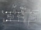
I struggle to understand wiring diagrams, so my first questions is: 1) If I want to eliminate the switch and hard-wire a new XO to the middle switch position, should I recreate the attached schematic? In other words, is my schematic XO equivalent to the original XO switched to the middle position? 2) For my own education, what function does the 14.4 ohm branch serve (or the 10 ohm resistor in the original XO), if any? and 3) I'll need to order the components (caps and resistors) so does anyone have suggestions? Basic caps and film resistors?

Thank you all!
IMG_9743.jpeg
 
Register to hide this ad
Your schematic looks good to me. The 14.4 ohm is just part of a voltage divider and shunts some of the signal to ground because the tweeter has higher sensitivity than the woofer. You normally see the shunt resistor after the series resistor, but if it works, it works. A good poly cap and non-inductive power resistors are the norm for crossovers. Parts Express has a few options for you, but you won't find exact values for those resistors. I would probably try a 15 & 7 ohm, but you could combine a few values in parallel or series.
 
Your schematic looks good to me. The 14.4 ohm is just part of a voltage divider and shunts some of the signal to ground because the tweeter has higher sensitivity than the woofer. You normally see the shunt resistor after the series resistor, but if it works, it works. A good poly cap and non-inductive power resistors are the norm for crossovers. Parts Express has a few options for you, but you won't find exact values for those resistors. I would probably try a 15 & 7 ohm, but you could combine a few values in parallel or series.
Tom, thank you for this reply. Glad to know I didn't muck up with schematic.

I looked around Parts Express and did some additional read on AK. I'm thinking I'll go with the pricey top of the line Jantzen 4.7uF and maybe a 0.22uF in parallel to get as close as possible to the original 5.0. It's a passion project, so I figure why not spend a little extra. For the series resistance, this Dayton Audio 6.5 ohm is pretty close to the 6.6. And for the shunt, the same Dayton Audio 7.0 ohm + 7.5 ohm gets darn close to the original 14.4 ohm. Does that all seem reasonable?
 
The "Standard Z" Jantzen is also decent at a fraction of the cost of the "Superior Z". Just stay clear of the Jantzen "CrossCaps"
 
Back
Top Bottom