Hi
FlaCharlie,
reading this again, you are actually stating that
EF95 tubes (lower plate current) are causing an increase in voltage, therefore, the ones
Dr.Ears loves (
EF95) are pushing the limits of the unit. Is this correct, perhaps a typing mistake, or am I reading it incorrectly? If so, please warn
Dr.Ears for engaging in risky behaviour.

")

.
I know the answer but I'm being a bit lighthearted here, so please don't take offence or get unduly upset. We all need to lighten up a bit and keep this friendly. We need more laughter and try not to take ourselves too seriously, especially in these challenging times.

No offense taken and I apologize if I'm coming across too heavy on all this.
I'm just saying that you have to look at all the factors that make one tube different from another and take that into account when you try them.
Edit: just noticed the recent posts but haven't read them yet . . .
As it turns out, my concern about the tubes with lower heater current is misplaced.
The original version came with the Chinese 6J1 which has a 175mA heater, as do the 6AK5, 5654 and EF95.
Earlier, you linked an "exotic" variant labelled Rod Rain Audio which gives the buyer a choice between 6J3P and 6K4P tubes. Those tubes, along with the 6AG5 / 6186 and 6F31, all have 300mA heaters. And some other tubes you listed as subs, 6J5P / 6AH6 / 6F36/ 6485 have a heater current of 450mA.
I'm used to dealing with transformers which have high voltage windings and heater windings for which specs are usually available. So you have an idea about how much current each winding can safely handle. Looking at the schematic posted earlier, I can't say that I fully understand the (internal) PS circuit used in these. Certainly the 1N4007 diodes are able to handle more current than is being used but I have no idea about the limitations of the other components.
I also realized that, back in the thread a ways, someone measured their voltages for me when I was setting up my breadboard. The heaters were actually a bit lower than 6.3v with a 12v PS and and almost 5% over with a 13.8v supply. It's best to stay within 5%. Those voltages were taken with tubes whose heaters draw 175mA.
So heater voltages should not be an issue but I'd still be concerned with the voltage on some of the caps. As I recall, with a 13.8v supply, the measured voltage on the 35v cap was at, or slightly above, 35v. They could have used 50v parts, which is what any competent designer would do, but they apparently didn't want to spend the extra 6 or 8 cents.
Quality caps can handle some abuse but who knows if the caps in these are really name brands or counterfeits. Unfortunately, this is always a concern with Chinese gear. When someone identifies one counterfeit part, as
@Rob43 did, it makes you wonder about others.
You might want to measure the heater voltages with the higher current tubes and keep an eye out to see if you notice anything running hotter than normal, which would be a sign of stress on the circuit.
As you can see from the pinout, they are Pins 4 and 5. Of course, the pin diagram is the view from the bottom of the tube.
Again, I'm not familiar with these types of (internal) power supplies and how they react to over current conditions. In a normal tube amp if you put too much current on a winding, the voltage will drop below its nominal (in this case 6.3v) rating and the transformer will run hotter, indicating stress.
Since you're into experimenting, you should consider building a more traditional preamp that uses these tubes at the operating points they were designed to use. See my posts and schematics earlier in the thread. It would be an eye-opening experience for you.


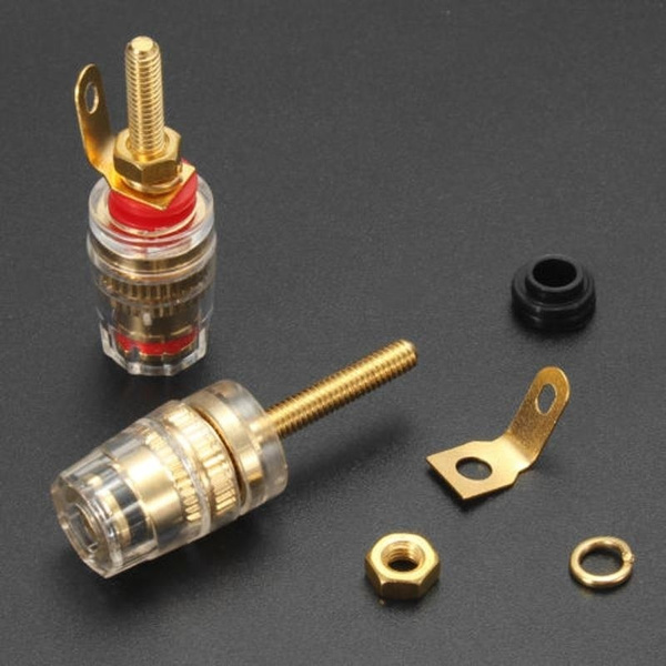
 why not drill two holes in the back and put some very nice binding posts