• The move to the new server is done. There are some software and database maintenance updates in process. This has us passing the hat around to help out. We appreciate any donations. Seriously, even a dollar helps. The payment page may be found here - https://www.audiokarma.org/support.html

Kenwood KA 770D DC offset

EC1

Super Member
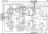
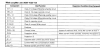
The offset are measured at 46 and 56 mv for left and right, not great but it is OK as well, I think. Still, would like to see better if I can. There is no adjustment for the DC offset, is there anyway I can improve these numbers? Looking at the driver transistors (I think) or differential transistors, there are 1st stage, 2nd stage, are these the right ones possibly would bring down the DC offset? Thanks.
Screenshot 2021-10-10 120349.png Screenshot 2021-10-10 120720.png
 
Register to hide this ad
If it were me, I would start with 1st stage diff, then 2nd, then 3rd. Use matched suitable replacements.


Rob
 
Rob, thanks for your input.
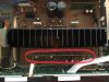
Another question, the board holding these differential pairs is right in front of the heatsink with very limited access.
808D9BFA-2868-4CF1-87FC-52EC7A4E7F03.jpeg
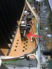
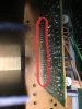
and this board is connected to the main board through 3 white color connectors with serial of legs soldered to both boards. I seems can’t pull the board straight up and the only way is to desolder these legs to loose the board holding the differential transistors pairs. Does this look right to you? If that is the case, it seems no chance for me to try each pair one by one, that will be a lot of soldering and desoldering back and forth? Or there is some better way to disconnect them?
6DA08742-F352-4965-BFB9-638C9C8E4F48.jpeg 7B33429C-6EB0-4EE1-A95F-55B3F3CB47D8.jpeg 19A320E5-1A45-4E5A-B52F-55C0A7A75FC4.jpeg
 
I think I would leave well enough alone given the job that is going to be. Unless you think you need to re-cap it, and even then I'd use a cheapo Radio Shack solder sucker and not remove the board unless I had to.
 
I would think there should be a better way to perform this task. But I just can’t think of others with my limited experiences. There are total of 33 tiny joints to be done. Maybe it would be easier to desolder the output transistors (18 joints comparing to 33), remove the output transistors along with the heatsink to open the back side access totally. But with what I could be able to achieve which is bring down the DC offset, it might not worth the trouble.
 
You could pull the board and replace all three sets. It would suck if it was worse when you put it back together.:D

That said, 56mv isn't horrible. Do you see any woofer movement when connecting speakers? Do you get a small pop?

Rob
 
Yup, that board basically is sandwiched in between the front tone board and the heatsink with no easy access. I can remove the front board and also unbolt the output transistors from the heatsink and remove the heatsink to open it up. Or total desolder those 33 pins and pull that board out totally. As you said, it will be fun to see the DC numbers not improving at that time. I might just do the whole recapping if I am really into it that far but I don’t think I am ready to do that yet.
No, it runs well not observing any weird thing yet. I still imagine there should be an easier way but looks like not. :(
 
Back
Top Bottom