

You are using an out of date browser. It may not display this or other websites correctly.
You should upgrade or use an alternative browser.
You should upgrade or use an alternative browser.
Lowering DC Offset in amps?
- Thread starter Quakeos
- Start date
Register to hide this ad
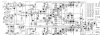

BTW your going to have to enlarge that schematic a bit.I misplaced my magnifing glass.channel A starts off clear and distorts as the volume is increased.
Root cause -- could be lots of things.I highly doubt that the dc offset is the root cause. What configuration is the power supply ? Just about anything could cause your issue.Need to check for a healthy power supply for the A channel.
Last edited:

sp58
Active Member
There is a thread for this
http://audiokarma.org/forums/index.php?threads/amplifier-distortion-dc-offset-and-you.5634/
Good luck
http://audiokarma.org/forums/index.php?threads/amplifier-distortion-dc-offset-and-you.5634/
Good luck

ryuuoh
FFXIV Summoner
https://elektrotanya.com/perreaux_3000b_sch.pdf/download.html
Watch out for the click-bait.
Watch out for the click-bait.

Quakeos
New Member
I’ve read that thread and it’s amazing However doesn’t offer much solution. , I am going to replace all the transistors on the board however(not the mosfets of course ). I wouldn’t have a clue what a power supply configuration means but I will put up a photo soon of the smock internals and a blew up schematic , however it is blurry. I can tell you though It’s a massive copper foil PSU unit.
I’ve checked every cap to Be healthy , and as far as amps go it seems like a minimal complexity board (still too much for me am I right haha)
I genuinely hope changing all transistors will fix it, And as mentioned the mosfets in this amp are absolute unobtainium and if they could be a cause of this distortion I’m rooted
I’ve checked every cap to Be healthy , and as far as amps go it seems like a minimal complexity board (still too much for me am I right haha)
I genuinely hope changing all transistors will fix it, And as mentioned the mosfets in this amp are absolute unobtainium and if they could be a cause of this distortion I’m rooted
LOL good one..I’m rooted

OMGCat!
Super Member
I’ve read that thread and it’s amazing However doesn’t offer much solution. , I am going to replace all the transistors on the board however(not the mosfets of course ). I wouldn’t have a clue what a power supply configuration means but I will put up a photo soon of the smock internals and a blew up schematic , however it is blurry. I can tell you though It’s a massive copper foil PSU unit.
I’ve checked every cap to Be healthy , and as far as amps go it seems like a minimal complexity board (still too much for me am I right haha)
I genuinely hope changing all transistors will fix it, And as mentioned the mosfets in this amp are absolute unobtainium and if they could be a cause of this distortion I’m rooted
Just randomly changing all of the transistors on the board without knowing which do what could very well have you with worse offset than you have now. Likely the diff pair need to be matched for gain to get your offset down. If you throw a random pair in there you could easily make it worse.
Isn't the other thread you have open about this amp about the same issue?

elnaldo
Lunatic Member
With a matched pair of transistors at the differential pair, being the rest of the circuit within specs, you should have a reasonable low DC offset. Though, I've lowered the factory DC offset in 2 amps (one of them a Technics SA-400), modifying the value of one or 2 resistors in the differential pair network, thus reducing or increasing the current flow in the pair, or in one of the transistors.
But you need a working amplifier, to trust the differential pair is closely matched, and THEN try to do small modifications to those resistors while monitoring the changes in DC offset.
If you search a thread "DC offset puzzle" you can see my workaround in one of the amps, along with a lot of explanations from experienced techs teaching me which resistors affect the DC offset.
Also, some reading about "OCL amplifier" will show you the way that differential pair works correcting the DC offset, and why it must be matched for gain.
But you need a working amplifier, to trust the differential pair is closely matched, and THEN try to do small modifications to those resistors while monitoring the changes in DC offset.
If you search a thread "DC offset puzzle" you can see my workaround in one of the amps, along with a lot of explanations from experienced techs teaching me which resistors affect the DC offset.
Also, some reading about "OCL amplifier" will show you the way that differential pair works correcting the DC offset, and why it must be matched for gain.
Last edited:

petehall347
the brandy coffee man
have you checked the idle bias ?

dly66
Addicted Member
Both times I have had high DC offset it was the pair at the front of the amp circuit. One amp was a differential pair design with no trimmer. Another an older SS amp type that did not use a differential pair and the trimmer could not get DC much below 200 mV before the front pair was replaced. It seems the PNP/NPN pair at the front of that amp circuit controlled the DC offset.
Two points.
1. There is an offset adjuster in the circuit shown. There are 2 adjustable presets. The one in the centre of the drawing is to adjust driver bias current and the one which is shown below and to the right of this is for adjusting output offset.
2. The fact that the 'bad' channel starts of O.K. and then starts to distort as the volume is raised would suggest that you have a problem which is either temperature or current based. I would try running it first with no input and then check the voltages across the Zener diodes. Then start to turn the volume up and see if that Zener voltages change. This would indicate overdriving of the output MOSFET gates.
As you have a good channel, at least you have something to compare the bad channel to.
1. There is an offset adjuster in the circuit shown. There are 2 adjustable presets. The one in the centre of the drawing is to adjust driver bias current and the one which is shown below and to the right of this is for adjusting output offset.
2. The fact that the 'bad' channel starts of O.K. and then starts to distort as the volume is raised would suggest that you have a problem which is either temperature or current based. I would try running it first with no input and then check the voltages across the Zener diodes. Then start to turn the volume up and see if that Zener voltages change. This would indicate overdriving of the output MOSFET gates.
As you have a good channel, at least you have something to compare the bad channel to.