• The move to the new server is done. There are some software and database maintenance updates in process. This has us passing the hat around to help out. We appreciate any donations. Seriously, even a dollar helps. The payment page may be found here - https://www.audiokarma.org/support.html

Marantz 1060 Recap

ZeroG

Super Member
Inspired by this great thread on recapping the 1060, I've ordered the caps and should be starting this week. One question I have (bet I can't ask just one...):

in the thread
http://www.audiokarma.org/forums/showthread.php?t=185299&highlight=1060


Echowars and others discuss upgrading the main power cap and two output caps. The main 10,000 uf 75V I have no problem with. EW recommended the 8200uf 50V for the output caps, but I already have a new pair of Nippon Chemi-Com 8200uf 63V caps that I could use.

I've noted that the basic rule of thumb for recapping here is to maintain the same uf, and go one voltage step higher.

In this case, because the power rating has already been increased, would the voltage increase from 50V to 63V be significant, and could it cause too much voltage to flow and harm something?

Should I stick with the 50V caps?

Thanks! I'm really excited about renovating this sweet sounding amp, and I sure don't want any mistakes.
 
Last edited:
Register to hide this ad
No problem using the 63V caps. Stick 'em in there! The voltage rating is what the cap can withstand, say you put a 35V cap in a circuit where the signal is 35V. That's a bad thing. A one or two step higher voltage rating is a good thing.
 
Recap Questions

Greetings,

Roger that. Well, the caps have arrived, I've cracked my knuckles and am ready to proceed. I plan on replacing the power and filter caps first, then the 800 board, the 700 board, & so on. When that's complete I'd like to try upgrading with some film caps and transistor upgrades as have been pointed out in other threads.

Question about the main caps:
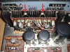
I splurged for the Mallory 10,000uf 75V screw type power cap. Would it be advisable to clip the entire lead off the old and solder to a ring terminal (+ heat shrink), or to unsolder each wire and stuff a ring terminal with them? It seems that clipping the lead would produce the easiest and neatest connection, since there isn't much wire slack, but Is that considered good practice to do? Any side effects? (This 1060 is a favorite of mine and I want it to survive the surgery).

Question about the P700 board removal:
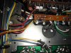
The thermistors concern me, since they aren't available any more. I practiced on an overworked, previously repaired by others, dead 2215B for a while, and although I wasn't able to revive it, I learned a few things and it's made a good parts unit. (it donated the power switch to the 1060). When I removed the P700 from the 2215B, the thermistor wires broke off from the thermistor. This looks to be the most challenging board to work on.

I would like to reinforce the thermistor wires at the thermistor to prevent them from breaking, and thought that a glue gun might work, or epoxy clay. Or should I do that and remove them from the board by unsoldering the wires from the board rather than removing the clip that binds them to the heatsink.

Any thoughts on this?. This is my favorite amp and I want it to really sing when I'm done with it.
 

Attachments

  • Marantz 1060 009 (Small).jpg
    Marantz 1060 009 (Small).jpg
    70.6 KB · Views: 154
  • Marantz 1060 014 (Small).jpg
    Marantz 1060 014 (Small).jpg
    61.8 KB · Views: 135
Last edited:
If you have enough slack in the wire to clip them off, then you can do that. I did it on a 2220B that I just finished. Desoldering the wires usually leaves them in pretty rough shape, they are usually wrapped tight around the original terminals. Reputable techs that I know use the ring terminal you are talking about, it looks really nice. Pay very close attention to the polarity of the filter and the coupling caps, I learned the hard way on putting those in wrong. :no:

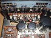
Are you talking about the little bias diodes on the heatsink? I highlighted them in the picture with red arrows. You can just unscrew the little clamp to free the diodes. Try not to strain the wires, you already found that they are delicate. I didn't have any problems just unscrewing them. I'm not sure if you could get away with reinforcing the wires.
 

Attachments

  • Marantz 1060 009 (Small).jpg
    Marantz 1060 009 (Small).jpg
    53.1 KB · Views: 133
Regarding the cap leads, I was thinking about clipping the "L" part of the terminal off of the old cap, then soldering the whole thing to a ring terminal. You're right, there's not that much slack in the wires, so I would prefer to make it easy and neat. Nothing wrong with trying it, I guess. I can always pigtail a little more wire, but I'd like to keep it neat.

The red arrows point to the thermistors - them's the ones. I don't want to break the leads, since I found out how fragile they can be. I know the clip unscrews and all - but sometimes it doesn't take much to break off a lead. I wanted to reinforce it before unscrewing the clip, just to make sure. Sometimes the lead can come off just by the heat of soldering, due to age and deterioration.

What program are you using to draw on the photo?
Thanks
 
If you do want to desolder the wires from the terminals, it would be easier if you cut those terminals off. Heat shrink can make things look really nice too. I was thinking that if you put glue on those leads, it might insulate the thermistors and cause too much heat to be retained. I don't know how much heat they generate though. Maybe try a little bit of soft putty that you could remove later? I used Microsoft Paint to draw on the picture. :D
 
Progressing Along with Marantz 1060 Recap

I've been taking my time and recapping a section at a time, then testing out the amp and noting the differences each board's upgrade makes.

So far, I've recapped the large main caps, the P800 board, and the P400 tone board. I am waiting on transistors and film caps for the P700 board, since I don't want to disassemble it twice.

I used axial film caps for the two 1uf bi-polar caps on the tone board. They are the Cornell-Dublier MPP 10% caps, but they were an available replacement for the bi-polars that I neglected to order. After break-in, I was pleasantly surprised at the difference the MPP caps made. The Panasonic radial MPP 5% caps are due in Saturday or Monday and I didn't want to wait. Now I might just leave the axials in- how much better could the Panasonics be?

One thing I do want to mention: This amp seems to run much cooler than I remember. Hardly gets warm at all under low to moderate listening levels. I used the larger main caps per Echowar's recommendations - the screw-type Mallory 10,000 uf and the 8200uf filter caps with the 1uf bypass caps. Do the larger main caps have an effect on the temperature of the transformer by taking on some of the load?

One cool side-effect of the main cap upgrade I can vouch for is that it sure takes a while for the added capacitance to drain out when the amp is turned off. In fact, when I have a separate pre-amp hooked up and I leave the preamp on and turn off the amp - it seems like it plays for another 3-4 minutes.

So far I am a quite a happy camper with the sonic improvements.
 
Back
Top Bottom