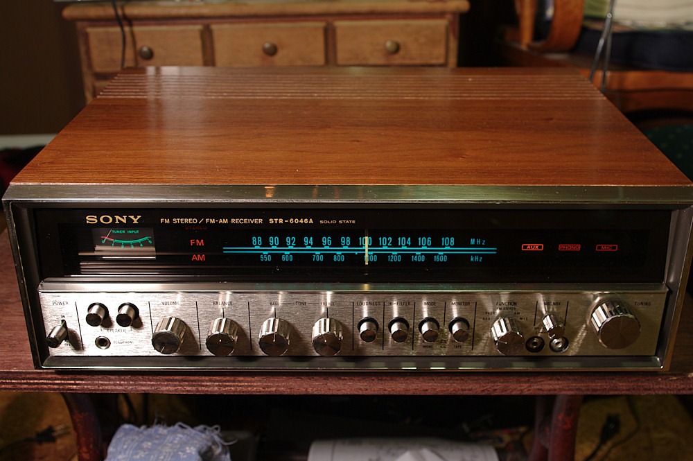
Minor Scroe - Sony STR-6046A

jheu02

AK Subscriber
Subscriber
Saw an ad in our local paper for this receiver. $10 - doesn't work. I figured that if nothing else it could be parted out. Picked it up and the only thing not working is the FM section according to the gentleman I purchased it from. It's had a basic deOxit and Faderlube treatment, some dust blown out, general cleaning of the faceplate and I rubbed some rejuvenating oil on the case. DC offset on the speaker terminals: 28.4mV R side and 4.6mV L side. I'll do some troubleshooting later when I have more time...reflow solder joints on the FM board, etc. Writeups sound good about the soundstage, but I'll probably recap it before it gets too much use. Gotta love the green dial though. Anybody have a Service Manual for it?

12508412285_2546012196_o.jpg


12508885734_9c90fd493b_o.jpg


12508413395_5138e939ca_o.jpg


12508412855_91d05bc95d_o.jpg
 
Register to hide this ad
wow, that is one clean, nice looking Sony!!!
Is that an AM antenna internally mounted?
Looks like it should be easy to work on. FWIW, I have a 6045 that had FM multiplex problems, re-flowing the solder joints cured it.
 
I have one of those and a 6036A also. They sound good. Nice score. Cleaned up really good. 20-40 watt receivers were the only things I was finding at garage sales last year and $10-$30 was the going price. Ended up with way too many.
 
wow, that is one clean, nice looking Sony!!! FWIW, I have a 6045 that had FM multiplex problems, re-flowing the solder joints cured it.

Yep, AM antenna internally mounted . Nice to know it may just be bad solder joints for the FM. It does sound good, but I was noticing a bit of hum with the tape monitor engaged. It didn't seem to change when the volume was increased, but I'm thinking that may also be related to a speaker thump when the power is turned on. Definitely time for a recap of at least the power supply board, but I'm sure I'll just do the whole thing.

Anyone else have the speaker thump going on? There's no relay protection circuit that I can see.
 
Looks like the service manual is available here:

http://freeservicemanuals.info/servicemanuals/download/Sony/str-6046.pdf

Not sure if there's a difference between 6046 and 6046A though.

John

I found that one, but it's for the basic model, not the 6046A. That one doesn't have the STK power packs, but uses TO-3 output transistors. Not sure what other differences there might be, but one good thing I found was the schematic. It was tucked in the Owner's Manual, so at least I have that.
 
Recapping Begins

Time to start the recap with what I have on hand and check for bad solder joints, loose ground connections, etc. Someone's been in it before because that orange axial cap in the 3rd photo should be a radial cap next to the other 3 light blue ones in the 4th photo. Those blue ones are Nichicons, whereas everything else was Elna. There's also a pair of black caps that look non original. I've also found some lifted solder tabs on the tuner board, so I'm having to do some point-to-point wiring along the circuit traces to make sure that isn't causing the lack of FM.

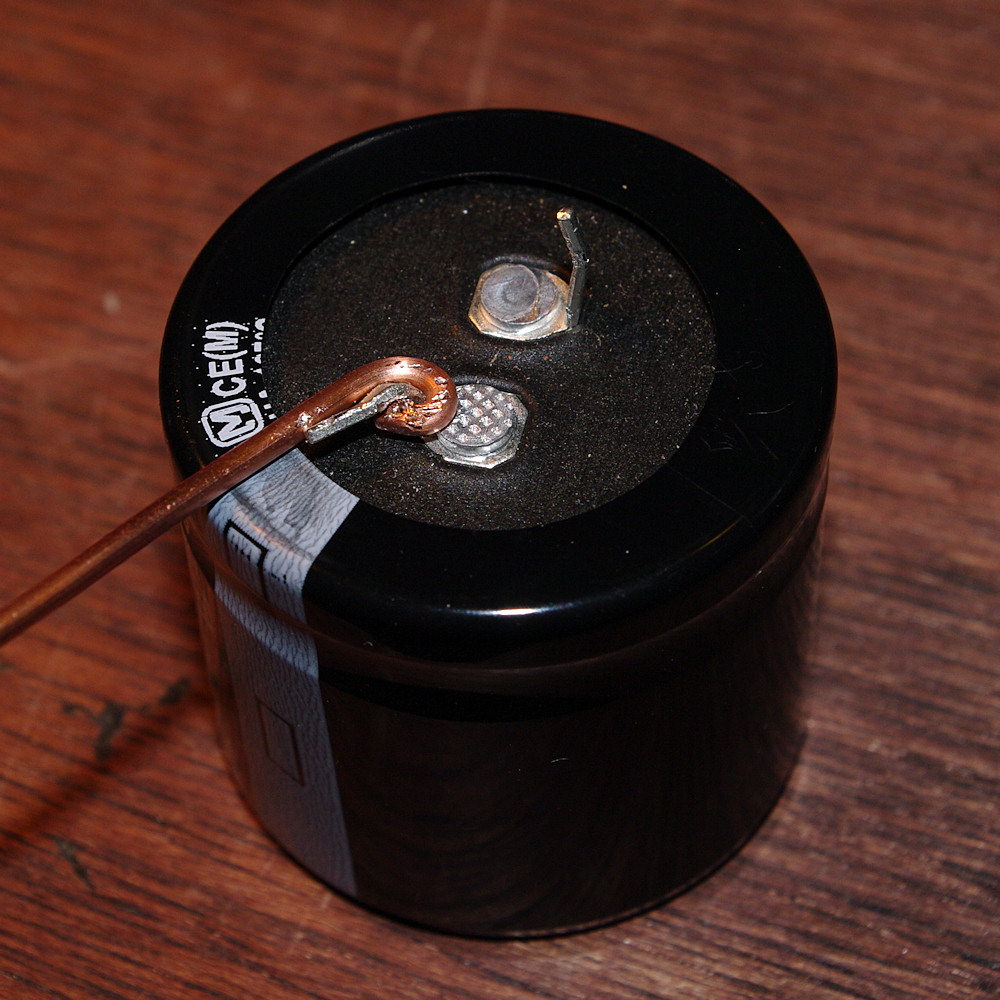
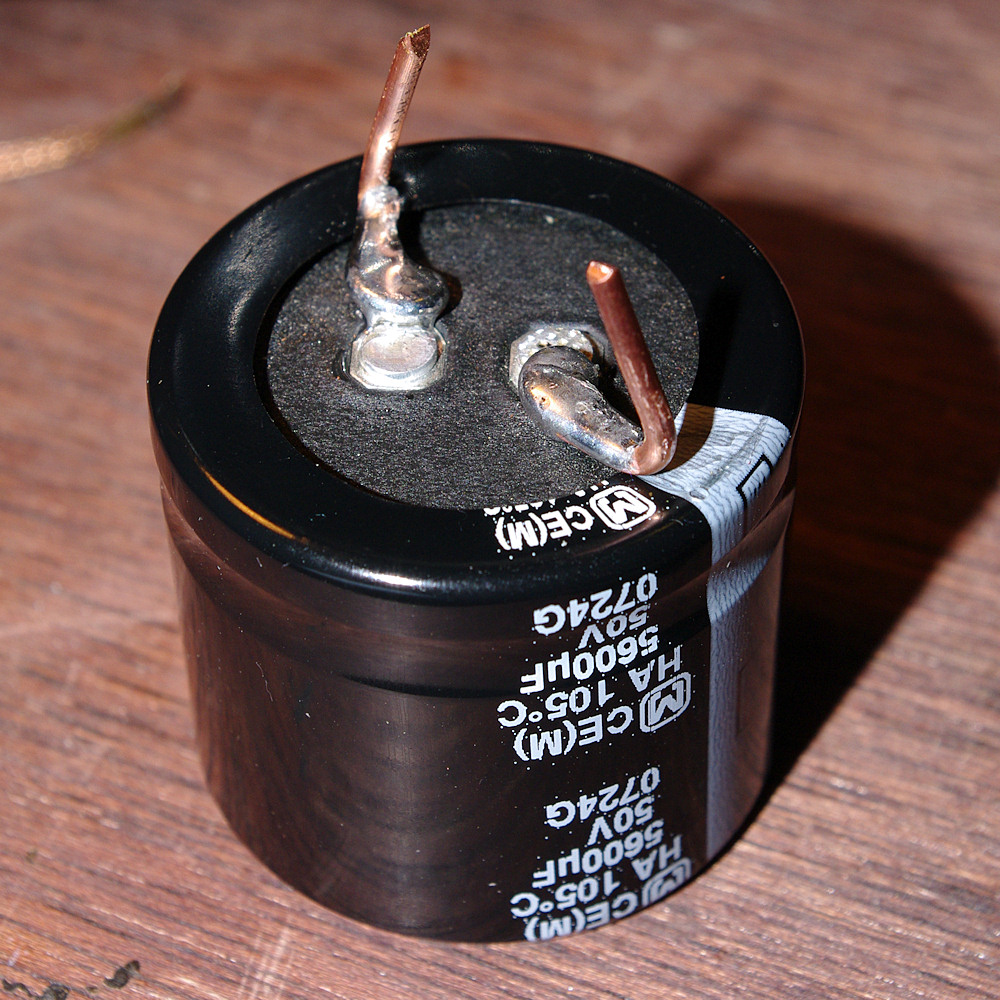
The PDF of the basic version is nice in that it lists tolerance changes that can be made for the caps, i.e. 3.3uF/50V +150% -10%. Comparing the schematic that came with the manual, and what's actually in the unit reveals that it looks like in many instances they already did that at the factory. For instance the main filter caps are 4700uF/35V according to the schematic, but what's in there are 5600uF/35V. Unfortunately, those caps are the old style 4pin with 22.5mm lead spacing. Most of the modern caps use snap in terminals with 10mm spacing.

So my possible options for the main filter caps are:

1 - Go with the snap-ins by bending one lug and running an extender wire to the other connection point. This allows me to use TSHA or KMH series caps at 5600uF/50V.

2 - Re-stuff the cans with the above cap choice doing the wiring internally. Possibly more stable this way, but definitely more work.

3 - Use 4700uF caps like the schematic calls for. I could then use standard radial lead caps like the Nichicon PW series since the leads would be long enough. This is the easiest solution but will decrease filtering capacity unless I parallel with a 1000uF cap somewhere.

If it were yours, how would you proceed?
Are there other options you can think of?

I'd like to stay with the high temp, low ESR caps like the TSHA, PM, PW or KMH, and I want to bypass them with film, so I'll need the space for those too.
 
Last edited:
Well, I've re-flowed the tuner board, but no change to the FM section, so I'll need to start checking the transistors and voltages. It's really no big deal if I can't find out what's wrong as I have several tuners I can use instead. Any thoughts on where else to look?
 
Well, I've re-flowed the tuner board, but no change to the FM section, so I'll need to start checking the transistors and voltages. It's really no big deal if I can't find out what's wrong as I have several tuners I can use instead. Any thoughts on where else to look?

Well, that would have been too easy!

I have a Sherwood S-8500 that has an FM tuner issue, you can just barely hear FM sound if you crank the volume, so I am thinking it has to be some sort of amplification issue. Do you get anything similar?

I will be following to see what the experts advise you.
 
:thmbsp: Hey that Sony STR-6046A receiver is a pure classic and for $10 bucks I say you did excellent and consider that a very good score. I have the Sony model receiver and the thing is I was originally looking for the Sony STR-6046 that I remember my brother had back in the day (70's) but happen to come across the 6046A instead for $25 bucks on CL.

You sure cleaned it up beautifully, that thing looks gorgeous! :tresbon:

Thanks for posting and sharing! :D

EDIT: Just to give you a notice, currently there is a Service Manual on Ebay for the STR-6046A?
 
Last edited:
Caps Arrived!

I got to work on my Sony today as the rest of my caps arrived from mouser. I decided to go with Panasonic TS-HA caps for the power supply even though they're 2-pin snap-in caps vs the 4 pin originals. Little did I know at the time that 14 gauge Romex is the exact size of the holes in the circuit board. :smoke:

I was originally just going to extend the Negative Pin, but the offset spacing made the caps not line up quite right with the holes. Had I just decided to do all 4 pins from the outset, the front cap in Pic 3 would sit a little more even. Oh well. Other touches were to add a little solder to the wire wraps to ensure a good connection. Hopefully when I do it to the tuner board, or the new caps, will bring the FM back to life. Hopefully the issue isn't with the proprietary red box in the last pic.

Prepped for soldering
12785914015_8b0e43c873_o.jpg


Soldered
12786018033_449538c870_o.jpg


Installed
12786343034_a321a172c9_o.jpg


Power Supply Overhead
12785914815_267f119ddd_o.jpg


PS Trace Side w/bypass caps
12786016023_14bbcc7f05_o.jpg


Tuner Board
12786344334_7ffbd37596_o.jpg
 
Rest of the Caps

Finished off the rest of the main board. There were a couple that were a pain to get to...had to remove the dial reflector box and move some wiring around a little to get the iron in there. I didn't feel like taking the whole board out and all that would involve.

Some Pics

12799646753_357fef7d6c_o.jpg


12799959484_7aae95c3ff_o.jpg


12799961614_6a90b46a8b_o.jpg


Caps used were mainly Panasonic FM, FC, FR and Nichicon UKL. For the 1uF 'lytics I used Nichicon KWs except for the tone controls which got Elna RFS. ChemiCon KZE also got used once I think based on what I had on hand, and Panasonic ECQ film caps for the bypasses.

I still haven't gotten the FM section working and there's still the power thump and hum. I was really hoping that replacing the main cans would have cured it, but there must still be a grounding issue somewhere.

Any help on diagnosing the thump and tracking down the hum is appreciated.
 
So, the thumping/hum showed up after the recap? Suspect one or more of those wires that you had to move around. Specifically, examine each and every ground. Look for a broken wire just inside the insulation.

Those twist-on wiring connections were the state of the art in the 70s. Lots of vendors used them including the computer industry. The wiring, however, didn't really like being moved around after installation hence the suggestion. If its hum in both channels at the same time, focus on the power supply, too.

On the FM problem, check all voltages from the power supply. Then follow each of the voltage rails down through the FM sections. There will be dropping resistors and an electrolytic cap where the voltages are lowered. Make sure each of the lowered steps are all in spec, too.

If those check out, you'll need to start chasing the signal back into the stereo decoder and into the IF strip if that checks out. First things first, though.

Cheers,

David
 
The thumping and hum were there all along. I was hoping that the recap, which I was going to do anyway, would fix it. The wires weren't moved too much, but knowing that wire wraps didn't always stay nice and tight, I hit them with some solder. I did start another thread with the specific problems and what I've done to diagnose so far since this thread wasn't so much a rebuild thread at first, at least title-wise. Thanks for the thoughts so far.
 
Nice solution to getting the big caps to fit. What are those light bulb looking things in back of it?

Also wondering what caps you bypassed with the ECQ's.

I'm not sure, but this may be capacitor coupled, would that explain the thump?
 
Nice solution to getting the big caps to fit. What are those light bulb looking things in back of it?

Also wondering what caps you bypassed with the ECQ's.

I'm not sure, but this may be capacitor coupled, would that explain the thump?

The lightbulb looking things are labelled CB651 and 601, but on the schematic SB651 and 601. The symbol used for them is a circle with half-circles inside making a Yin/Yang looking thing, but I haven't come across it before. They are one of the last components prior to the speakers, so they certainly could be suspect.

I bypassed the main filter caps and the other supply caps near what I believe are the driver transistors. I'm really suspecting possible power switch arcing because the pop/thump is immediate. So the first thing I've got to do is get at that switch and the combined R/C that's attached.
 
I think jegor ID'd something very like that as being circuit breakers in another thread. Protection element of some kind, anyway... they wouldn't likely cause thumps at all, but you could bridge across them & see if that changes anythingm if you want to eliminate them from consideration.

John
 
I think jegor ID'd something very like that as being circuit breakers in another thread. Protection element of some kind, anyway... they wouldn't likely cause thumps at all, but you could bridge across them & see if that changes anythingm if you want to eliminate them from consideration.

John

They look intact. Numbers on them are 22sc2 but that doesn't pull up anything. The basic model schematic shows 1.25A fuses before the speaker terminals, so I'd say that they are definitely for protection, but it could be to protect the power amp modules from shorting the speaker wires together.

Here's a photo of that section of the schematic.
 

Attachments

  • image.jpg
    image.jpg
    96.9 KB · Views: 56
Back
Top Bottom