• The move to the new server is done. There are some software and database maintenance updates in process. This has us passing the hat around to help out. We appreciate any donations. Seriously, even a dollar helps. The payment page may be found here - https://www.audiokarma.org/support.html

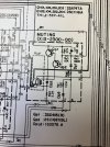
Muting Circuit Function

gort69

AK Subscriber
Subscriber
Hi folks,

I have a Trio KA-9300 which is essentially the Japanese domestic market version of a Kenwood Model 500/600 Supreme integrated amplifier.

This model has what the schematic refers to as a “Muting” circuit, whereas the 500/600 does not.

My question is - what does it do?

Thank you!
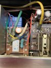
IMG_2838.jpeg
IMG_2839.jpeg
 
Register to hide this ad
The "mute" button typically cuts the output.
My pre-amp -Adcom GFP-815- has a mute button and it kills the output. I use it when switching sources to eliminate any pops making it to the amps and then the speakers.
 
Thanks for the reply. I failed to mention that there is no “mute” switch or button on this amplifier
 
Gottcha.

I'm guessing it mutes the output briefly after powering the unit on.
I agree, I see a relay, so it's most likely a protection circuit, or clicks on once the voltages come up so you don't hear any unwanted pops or clicks, etc at startup. Lots of equipment has these types if circuits. Usually in a power amp or amp section. I had a couple preamps with relays as well.
 
It looks like the relay mutes more of a line level signal, based on the pots in the signal line going into it. Without more of the schematic, it's hard to say much more, but perhaps a mute when sources are changed? Since it does not seem to be in the output, power up muting doesn't make as much sense as it might . . .
 
Thanks for the replies guys

This thing does have a speaker protection relay in addition to this reed relay in the muting circuit.

I’m not much for reading schematics -actually I suck at it - but I can tell you that this relay is in between where the signal exits the filter section and before the power amp section.

I have a PDF of the schematic, but it is too big to post here. I could email it to somebody if they’re as curious as I am, but it is strictly a curiosity thing on my end as the amp works just fine.

Thanks again
 
Guessing it's for suppression of preamp pops.
Relay is activated when B+ comes up and Cp1 (through Rp2) charges up eventually turns on Qp2 then Qp1.
Audio (thick black line=left channel) is then switched through relay.
 
Back
Top Bottom