oscilloscope help

Sam Cogley

Last of the Time Lords
Subscriber
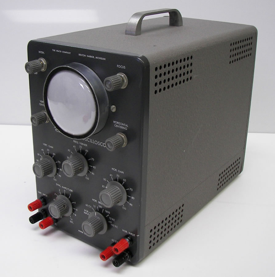
I picked up an oscilloscope today - a mid-50s vintage Heathkit OL-1. It was half-price day at the thrift store, so I got it for just under $10. So far, I've run into one big problem - I can't get the CRT to light up. I need to pull the cover to see if there are any obvious problems.

Is anyone familiar with this model and any known issues that might cause it to be dysfunctional? What do I need to get for probes if I do get it running? I'm probably going to have to buy a schematic and manual, none of the usual download sites seem to have one.
 
Register to hide this ad
Out of luck...

The new owner of the rights to the Heathkit name has strong armed all the usual suspects into removing their shared Heathkit material. The only site I know that still has free Heathkit info (Danish) doesn't have that one....:thumbsdn:

Anyone who wants the info on the site location can check my user profile.....:yes:
 
Apparently this thing uses 12AU7s for the amplifier tubes. At least I'm set in that department, I have a ton from the first Lowrey I dismembered.
 
First checks...crt filament lit...does it have high voltage to the crt

Even if the input amp and is not working and the horizontal amp is not driving the horizontal sweep you should be able to get a dot in the center of the screen... IIRC this 'scope did not have a beam killer although I might be wrong on that...

If you can see the crt filament and it is lit and you have high voltage to it then you can start to trouble shoot the rest of it...
 
Update - it's working, I think. After pulling the guts out of the case, I plugged it in and the CRT lit up. Some futzing around with the knobs and I got a trace in the center of the tube. Even with nothing connected, some knob-turning was giving me some patterns from the trace. Making life weird, it doesn't appear to have a grid on the display. The trace is very bright when the power adjustment is turned up. All of the tubes are lighting up, so I'm going to operate for now under the assumption that most things are behaving as they should. I'm sure it will need new caps, I'll worry about that later. Fortunately it has a ton of room to replace the multi-section cap, the original appears to be a six-cap monster.

Minor issues - one knob is missing, one is breaking, and the case has some surface rust (I'll sandblast and powder coat it sometime when I visit my parents). Whoever built the kit didn't wire up the off/intensity switch/pot properly, the only way to turn it off is to pull the plug.

What now? I know no more than the absolute bare minimum of information on the use of a 'scope, and I have no probes.
 
Just a few thoughts, I'm by no means an expert.

I do have an older scope among my vintage test equipment. The grid was illuminated by a bulb along the edge of the display. If yours is similar that might be the problem. Can't imagine that it doesn't have a grid at all. That would kind of eliminate most of the benefits of having a scope.

Be careful with the HV.
 
Fisher, I'm always cognizant of the HV in anything with tubes, though I'll be extra careful in here - I normally don't mess around with CRT stuff, not being a TV collector.

JBL,
Thanks for the link, I'll definitely take a look at that. Are there any recommended brands for probes?
 
The parts houses should have adapters....BNC to Banana plug on 3/4" centers..

Nice to see someone using "vintage test gear" on vintage audio gear...
 
I found a schematic on a French site if anyone is interested: ftp://216.24.174.245/heath/o11/

I disassembled the unit again - the only light in it is the pilot light, and everything on the CRT seems to be connected properly. No grid, I guess.

JBL, thanks for that info. I'll see if I can get something ordered.
 
Not my exact unit, but I found a picture of one online:
Set%208%20041.jpg


Now that I look at the pic, my CRT face is sitting at the back of that ring, not the front. Maybe the pilot light illuminates a grid display, and the out-of-position CRT is keeping that from working properly...hmm...I'll mess with that after work tonight.
 
It looks like the controls don't have anything that would relate to a grid. The vertical amp sensitivity shows steps like "20", "30", etc. but not voltage/div. So there is no point to a grid with this unit. It's really a display, but offers no accurate scale for making accurate measurements.

The CRT probably electrostatic deflection, as opposed to electromagnetic deflection. There's probably deflection plates to steer the beam. If this is the case and you can't get a spot, you can pull the X/Y deflection tubes and the spot should come straight up the middle.

....but it sounds like you were able to find the spot.
 
Oh well...I bought it mostly because it was cheap and I thought it would be fun to mess with. At the very least I should be able to see if bad things are happening, even if I won't have an exact number to apply to those bad things.
 
Oh well...I bought it mostly because it was cheap and I thought it would be fun to mess with. At the very least I should be able to see if bad things are happening, even if I won't have an exact number to apply to those bad things.

You could connect a reference signal, with a known voltage and mark the tube face with a frease pencil...
 
Back
Top Bottom