• The move to the new server is done. There are some software and database maintenance updates in process. This has us passing the hat around to help out. We appreciate any donations. Seriously, even a dollar helps. The payment page may be found here - https://www.audiokarma.org/support.html

Parasound HCA-3500 Upgrade & Question

hamrules

AK Subscriber
Subscriber
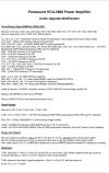
I'm trying to find if anyone has done the modification listing that is on the Interweb as I am trying to verify one item. It says to remove capacitors in R71 - R76, R79 & R80 locations which is fine but no mention of replacing them with the resistors called out in the schematic.
 
Last edited:
Register to hide this ad
IMG_5119.jpeg

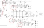
I’ve cut the area in reference to the resistors and circled them in red. They are all listed as a 10K @ 1watt.
 
Last edited:
Wonder if that resistors should be installed. I didn’t find anything on the Interweb from anyone talking about it. I did find a nice picture from someone that did the modification/upgrade list and they are just left blank. Blank it will be.
 
Last edited:
I'd probably leave the darn thing alone if you're unsure about why it would be one or the other, and the reason or not to tinker with them.

What's on the board is generally considered correct if there is a difference from schematics.
 
IMG_5132.jpeg
This is the list that Big Sky Audio used to do to them when they were still in business.
 
Last edited:
They're just cap bleeders, right? I don't think removing them would be good.
Yes I agree but Parasound had caps installed in those locations which BigSky said to remove. BigSky does not say to add the resistors that show in the Parasound schematic back in. Right now I have the one new cap installed like they say in the modification list.
 
Last edited:
IMG_5353.jpegIMG_5359.jpeg
IMG_5309.jpegIMG_5308.jpeg
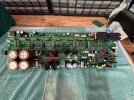
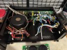
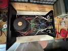
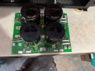
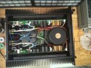
Power supply board done. Re-soldered all the wire screw posts to make sure they were good and re-enforced. Couple of new 50amp bridge rectifiers and a larger heatsink of copper that is sandwiched between the bridges and the chassis.
 
Last edited:
Hi John,

Looking very nice!

I think those are not bleeders, but are balance resistors for current sharing between the totem pole stacks of caps. Interesting that Parasound made an unmarked change and put in caps in those locations - what types of caps were in those resistor positions?

Not sure if Blue Sky had a good reason to omit the resistors, but those strings have 3 different types of caps which would have different leakage characteristics.
 
Most were .01uf and there were some in other locations that were .22uf along with a couple in parallel.
It was Big Sky Audio.
There is mention about some of this on DIY that John Curl acknowledged his design of this did not have all these bypass caps added.
Both sides passed DBT.
DCO is under 5mv.
Need to adjust bias now. Apparently it’s a little tricky as there’s two pots in series. Coarse then fine adjustment as I’ve read it referred to.
 
Interesting. Sounds like they were chasing the multiple, smaller value caps in parallel scheme. The comment you report from John Curl does not surprise me.

Looking more carefully I see there are actually large filter caps on those rails, so the resistors can serve as both bleeders and balance resistors.

Nice low offset!

The two pots in series are usually pretty easy to adjust - coarse setting, then fine. The Mitsubishi DA-DA15DC I have has the same arrangement. I like it - it's easy to be very precise.

Looking really sweet - great job, John!

Oops - Big Sky.
 
Last edited:
The left side under DBT is almost no glow. The right side under DBT glowed brighter. I took a BIAS reading on the right and it was around 14mv which is way to high. So far it’s looking good. Tomorrow I hope to get the BIAS adjusted both sides, at least for idle state we much is supposed to be around 3mv only. Then I need to feed a signal in and adjust for 20mv with the 3rd pot since I left the dynamic bias in place.
 
Have the right side set to 3mv idle bias.
Right side is at 2.6mv DCO.
Have the left side set to 3mv idle bias.
Left side is at 2mv DCO.

Next up will be dynamic bias.
 
Last edited:
Back
Top Bottom