
• The move to the new server is done. There are some software and database maintenance updates in process. This has us passing the hat around to help out. We appreciate any donations. Seriously, even a dollar helps. The payment page may be found here - https://www.audiokarma.org/support.html

QLS-1 Crossover Recap- experts opinions welcome-

4.3 Ohms means that the EMITs average around 8 Ohms individually. this is roughly my experience with them as well. i'm not sure what's going on with the crossover frequency calculation exactly, but the published frequencies seemed very reasonable compared to what i was hearing. three things to note, though:

1) when the rear tweeter is switched in, it's in parallel, so the total tweeter resistance actually drops slightly, closer to 3 Ohms. this would raise the frequency even more.

2) the crossover point you are calculating is the -3dB frequency. so one octave down from that is actually -9dB. from experience, this first-order slope means that you do have to take more care with these tweeters than you do in most speakers, but generally the fact that there are so many tweeters means that there is some extra built-in headroom.

3) i'm not sure you can just add the pot resistance on, since it's on the other side of the high-pass capacitor for the EMITs. can anyone definitively answer this?
 
I'm glad to see you jump in cdfac! I was sure all of my noodling was messed up.

IIRC, if the first-order slope is indeed a Butterworth and the high-pass and low-pass frequency is the same, then there's a 3db hump at that frequency.

If I got that notion right, then it seems likely to me that the EMITs cross a bit higher and the domes a bit lower than 4000Hz to sum flatter than that. Perhaps?

Those notions got me thinking that the electrical crossover frequencies could be extrapolated by calculating where the 2.5uf cap for the EMITs and the 13.6uf cap and .4mH coil for the domes would actually roll off. But it takes a nominal impedance to estimate that closely.

See? Just enough information and knowledge (?) to be dangerous. :D
 
if two adjacent drivers are each -3dB individually at the crossover frequency, then the total output will sum to 0dB. no issues there.

now we are sure that the EMITs are wired first in pairs (resulting in around 16 Ohms per pair), and then the four pairs are wired in parallel (which then gives around 4 Ohms, like you found by unplugging the tweeter array and measuring)? that is what i remember finding when i rewired my EMITs, but that was like 3 years ago and i can't find the diagram i made.
 
IIRC, this isn't the first time you've kindly corrected the flaws in my thinking (on this same subject no less). Thanks! :thmbsp:
 
4.3 Ohms means that the EMITs average around 8 Ohms individually. this is roughly my experience with them as well. i'm not sure what's going on with the crossover frequency calculation exactly, but the published frequencies seemed very reasonable compared to what i was hearing. three things to note, though:

1) when the rear tweeter is switched in, it's in parallel, so the total tweeter resistance actually drops slightly, closer to 3 Ohms. this would raise the frequency even more.

2) the crossover point you are calculating is the -3dB frequency. so one octave down from that is actually -9dB. from experience, this first-order slope means that you do have to take more care with these tweeters than you do in most speakers, but generally the fact that there are so many tweeters means that there is some extra built-in headroom.

3) i'm not sure you can just add the pot resistance on, since it's on the other side of the high-pass capacitor for the EMITs. can anyone definitively answer this?

The emits on my QLSs checked from 5.5 to 5.8 ohms Individually.
 
The emits on my QLSs checked from 5.5 to 5.8 ohms Individually.

That's the fuzzy math (or is it black magic :scratch2:) part of comparing DC resistance with nominal impedance.
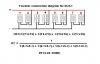
Mine measured anywhere from 4.9 to 6.6 ohms DCR when measured individually in the right channel, combined DCR is 4.3 ohms at the blue & blue/black wires.
 
The emits on my QLSs checked from 5.5 to 5.8 ohms Individually.

i must have been remembering wrong. if that's true, then the whole array should be reading less than 2.9 Ohms DCR plus the resistance of the wiring and solder joints. i wonder how that squares with Jim's 4.3 Ohm measurement? i was thinking that those secondary resistance factors would be smaller than ~1.4 Ohms, but perhaps not.

Jim, with these tweeters, the resistance makes up almost the entire impedance value. because there is no coil, inductance is low, and the geometry leaves capacitance small as well. when you did your measurement, you had unplugged the blue and blue/black wires, correct?
 
Yes, but my EMITs haven't had touched-up solder tabs and still have the original light gauge wire and quick disconnects at the terminal strip. This diagram must be correct then (below)...

...which led me to assume that the pot or rear EMIT must come into the combined impedance somewhere. I recognized from the impedance graph that came with some B&G Neo3 planars I had that the impedance may be nearly flat, just never saw anything related to the EMIT to confirm it..
 

Attachments

  • Twtckt.JPG
    Twtckt.JPG
    33.3 KB · Views: 29
Last edited:
Back
Top Bottom