

elbreapoly
New Member
Hi everyone,
I recently ran a thread discussing a newly acquired Scott Stereomaster 340-B that had a nasty homemade bridge rectifier mod on it. We concluded to remove it and this work has been done.
Now I must wander through the other steps in restoring this amplifier, and am in phase 2 and could use some feedback.
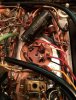
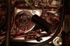
First, one can cap looked burned to a crisp from underneath, so I replaced it (photos 1 and 2) with a new CE multi-section (note the cap labels no longer match the schematic, but it is wired in the same way from which the previous cap was). See the first two photos for this work.
But with the replacement installed, and running the unit on low voltage (just enough to see if tubes lit), I was able to see that heater voltage seemed to be dropping from one tube to the next. This was especially apparent in the 4 7591 row, and other tubes such as the 12AX7s failed to light at all with the reduced heater voltage.
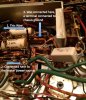
Then I saw something terribly wrong. Whoever this goofball is who installed that terrible bridge rectifier mod (in a place where the schematic calls for no rectifier), to say this most kindly, seemed to not be able to read the schematic, or simply didn't know what is going on (lest I think--I may be wrong as only being moderately educated in this area). So in photo 3: A black wire leading from one heater lead from the transformer (those nasty, big dark green wires and nasty soldering work) was directly connected to the chassis ground. My multimeter read zero resistance from the transformer lead to the chassis. So, I unsoldered that black wire and bent it upwards, as you can see in the third photo. I only didn't clip it off just yet in case I'm not understanding something here. But, the schematic indicates that the heater leads from the transformer go straight to each of the 4 7591s, then to two 6U8s before being grounded.
Then, still running at low voltages, the decaying heater voltage across the 7591s was no longer evident. Instead at this point, I measured higher heater voltage on tubes 1 and 3 in the 7591 chain, and lower on 2 and 4. The tubes lit up just barely with the low voltage, but clearly 1 and 3 were getting more power.
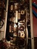
So now what should be my next step? In picture 4 you see four .1 MFD caps. Two of the four show leakage (about 15 kilo ohms from continuity on my multimeter, but I only measured while they were still in circuit and have not taken one of the leads out), but the other two do not and read zero continuity. 1 and 3 don't leak; 2,4 do.
SO, my replacement 0.1 MFD 600V caps have come in the mail. I'm ready to replace all four and will, probably one at a time to make sure I don't create some terrible short or whatever.
My questions for the expertise of AK members are then the following: how have I done so far (be brutal if needed); was my assessment correct in that the heater lead should not be directly connected to chassis ground; and finally, do you think these four caps are causing this issue, and if not, what steps should I follow to determine the problem?
Thanks in advance AK members, I couldn't do this without you!
I recently ran a thread discussing a newly acquired Scott Stereomaster 340-B that had a nasty homemade bridge rectifier mod on it. We concluded to remove it and this work has been done.
Now I must wander through the other steps in restoring this amplifier, and am in phase 2 and could use some feedback.
First, one can cap looked burned to a crisp from underneath, so I replaced it (photos 1 and 2) with a new CE multi-section (note the cap labels no longer match the schematic, but it is wired in the same way from which the previous cap was). See the first two photos for this work.
But with the replacement installed, and running the unit on low voltage (just enough to see if tubes lit), I was able to see that heater voltage seemed to be dropping from one tube to the next. This was especially apparent in the 4 7591 row, and other tubes such as the 12AX7s failed to light at all with the reduced heater voltage.
Then I saw something terribly wrong. Whoever this goofball is who installed that terrible bridge rectifier mod (in a place where the schematic calls for no rectifier), to say this most kindly, seemed to not be able to read the schematic, or simply didn't know what is going on (lest I think--I may be wrong as only being moderately educated in this area). So in photo 3: A black wire leading from one heater lead from the transformer (those nasty, big dark green wires and nasty soldering work) was directly connected to the chassis ground. My multimeter read zero resistance from the transformer lead to the chassis. So, I unsoldered that black wire and bent it upwards, as you can see in the third photo. I only didn't clip it off just yet in case I'm not understanding something here. But, the schematic indicates that the heater leads from the transformer go straight to each of the 4 7591s, then to two 6U8s before being grounded.
Then, still running at low voltages, the decaying heater voltage across the 7591s was no longer evident. Instead at this point, I measured higher heater voltage on tubes 1 and 3 in the 7591 chain, and lower on 2 and 4. The tubes lit up just barely with the low voltage, but clearly 1 and 3 were getting more power.
So now what should be my next step? In picture 4 you see four .1 MFD caps. Two of the four show leakage (about 15 kilo ohms from continuity on my multimeter, but I only measured while they were still in circuit and have not taken one of the leads out), but the other two do not and read zero continuity. 1 and 3 don't leak; 2,4 do.
SO, my replacement 0.1 MFD 600V caps have come in the mail. I'm ready to replace all four and will, probably one at a time to make sure I don't create some terrible short or whatever.
My questions for the expertise of AK members are then the following: how have I done so far (be brutal if needed); was my assessment correct in that the heater lead should not be directly connected to chassis ground; and finally, do you think these four caps are causing this issue, and if not, what steps should I follow to determine the problem?
Thanks in advance AK members, I couldn't do this without you!
Attachments
Last edited:

