• Please note that there are a few updates and clarifications made in the Audiokarma Rules, mostly relating to advertising and the addition of the new "Paying it Forward" & "Giving back" forums in the AudioKarma Audio Marketplace section.

Rotel RA-1210 Recap Gone Bad

milo63

Everett, WA
Subscriber
I'm back with hat in hands, another learning moment.

It's just 12 electrolytics, six per channel. What could go wrong?
No power at either idling current test point.
I did continuity from the A-Z pad to the furthest point on the trace to check for opens, all good.

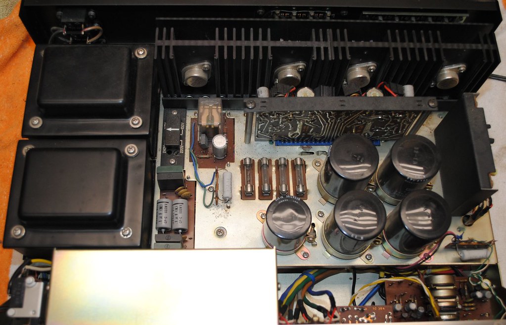
I replaced the two 100pf oil caps in the power supply and three 1000uf. I get 42V (+ and -) at the fuses (should be 48).

Does anything stand out as incorrect in the pictures?

Replaced caps:
49739327232_eecf0bc285_b.jpg


The nearly unreadable HFE schematic with no voltage points:

49739004136_c2b429877d_b.jpg
 
Register to hide this ad
Does Q01 & 03 have 42v at the collectors ?

I can't get to the back of Q1-Q4 without disassembling or risking catastrophe cross-grabbing. I do have 42V at C1, which is soldered to the same terminal as the wire going to the C1 collector.

My bad, I didn't try to adjust before diving in so I don't know if it was adjustable before.
 
Did the unit even work before you started?

That's the strange part, the guy I bought it from said one channel was bad, I did a DBT and hooked it up, sounded great for a few days before it got pulled out of rotation. Then I killed it.

I've checked amp board (and Q1-Q4) transistors in place and there's no shorts or opens (.5-.7 volt drop all around).
The preamp works fine when separated.
If the 42V at the input is adequate it has to be something on this board.

I keep thinking if I stare at these circuits long enough something will click, no luck so far.

Edit: And it's both channels, if it was just one I'd have something to start with.
 
Last edited:
Whats the resistance between F and K as well as R and U. Should be around 1 ohm.With the board removed from circuit. Emitter resistors integrity.
 
OK, I'm truly flummoxed now.
Function generator 10Khz into the AMP RCA, signal pulled off of E and V (output to speaker switch).

Time to take a step back and ponder. Too early for a beer.

49740128082_ece960721c_c.jpg
 
Ohm out your test pins to the emitter resistors.Look at the solder connections for your test pins.
 
Sending a 1K signal directly into the AMP input I get my ears blown off with a 1K tone.
Hook up CD player and it works? Still won't bias. I'll leave it on for a while and come back.
 
Ohm out your test pins to the emitter resistors.Look at the solder connections for your test pins.

I reflowed them, and tried to bias from TP 3 and K.

Trying to figure out if my amp board socket has some slop and not making good contact.
 
Sending a 1K signal directly into the AMP input I get my ears blown off with a 1K tone.
Hook up CD player and it works? Still won't bias. I'll leave it on for a while and come back.
Are the outputs getting very warm? As in over biased.
 
Is that a thermal cutout on the output? Doesn't appear to be any standard drawing of a relay even though there is one in the unit picture.
 
Back
Top Bottom