• The move to the new server is done. There are some software and database maintenance updates in process. This has us passing the hat around to help out. We appreciate any donations. Seriously, even a dollar helps. The payment page may be found here - https://www.audiokarma.org/support.html

RT 707 restoration

dgallagher

New Member
Hi everyone,

I’m starting a restoration project on a Pioneer RT-707 I’m a capable hobbyist at best but definitely still a newbie when it comes to servicing reel-to-reel decks. I’ve been spending quite a bit of time reading through this site and have already found a lot of great information here, especially the threads from smurfer77 and Trevor White

I’ll post pictures and updates as I go if it can add to there fantastic work, as my RT 707 was made in Feb of 1978 there may have been some differences, I’ll definitely have a few questions along the way.

The RT-707 is perfect cosmetically inside and out and everything functions with the exception of the counter, and the left channel seems to have slightly less output via the VU meter but it’s difficult for me to tell for sure. My plan is to take things methodically — clean and inspect everything first, establish a good baseline, then address anything that needs attention and eventually get into the electronic restoration and calibration.

Any advice, suggestions, or corrections along the way are very welcome. I’d rather learn how to do something correctly than simply replace parts without understanding why.

Here are pictures of the two decks I own, CT 500 ( I serviced tape mech and replaced all belts and set speed, fully functional sounds great,) it’s second inline for restoration, after the RT 707.


Looking forward to learning from everyone here!IMG_1741.jpegIMG_1736.jpeg
 
Last edited:
Register to hide this ad
Hi everyone,

I’m starting a restoration project on a Pioneer RT-707 I’m a capable hobbyist at best but definitely still a newbie when it comes to servicing reel-to-reel decks. I’ve been spending quite a bit of time reading through this site and have already found a lot of great information here, especially the threads from smurfer77 and Trevor White

I’ll post pictures and updates as I go if it can add to there fantastic work, as my RT 707 was made in Feb of 1978 there may have been some differences, I’ll definitely have a few questions along the way.

The RT-707 is perfect cosmetically inside and out and everything functions with the exception of the counter, and the left channel seems to have slightly less output via the VU meter but it’s difficult for me to tell for sure. My plan is to take things methodically — clean and inspect everything first, establish a good baseline, then address anything that needs attention and eventually get into the electronic restoration and calibration.

Any advice, suggestions, or corrections along the way are very welcome. I’d rather learn how to do something correctly than simply replace parts without understanding why.

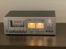
Here are pictures of the two decks I own, CT 500 ( I serviced tape mech and replaced all belts and set speed, fully functional sounds great,) it’s second inline for restoration, after the RT 707.


Looking forward to learning from everyone here!
 
Thank you.

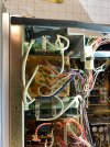
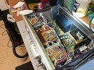
Took it apart to look and clean with a light brush and vac held back a ways deoxit f5 on switches lubed auto stop and lubed rollers, left the belt alone as when gear arrives I’ll dismantle it a lot further and the belt will be easier to get to. Waiting on the items below to get get started. I did purchase rebuild kit on eBay, don’t recommend, after digging into smurfer77 and Trevor White threads I’ll be headed to digikey a lot so wish I would have found there threads sooner.

FNIRSI LCR-P1 Transistor Tester, LCR Meter, Capacitor Tester, Auto Test​

FNIRSI 2C53T 3-in-1 50MHz 2CH Oscilloscope Multimeter DDS Signal Generator​

YIHUA 948D III Soldering Iron Desoldering Station​

With these and a few other items I should be able to get started. Any tips on soldering and de soldering temps for the pioneer board would be appreciated.


IMG_1683.jpegIMG_1689.jpeg
 
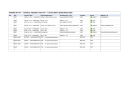
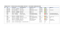
I plan on following the same path as Trevor White for the most part, So here is my first attempt at a list of components for first three boards I plan to work on. Obviously one at a time but I want to Oder parts in advance for couple of boards. The list shows component location type/value, digikey part number etc.. for me I included if testing/visibly inspecting and if I need to source the part or not as I bought a eBay kit so I have some of the components. Let me know if something is wrong or could be better, thanks.RWG-070 Control Assembly.pngRWR-053 Power Oscillation Assembly.pngRWX-154 EQ Amplifier Assembly.png
 
Last edited:
That’s the plan, I’m going to use to for a couple of months while collecting all the required bits and bobs to start restoration. Hope to get head cleaner and demagnetizer today, Have some good classical prerecorded 71/2ips tapes and some RTMLPR35 tapes to test recording
Besides test tape mentioned here I would like to make my own tone tape based on machine as it is now before restoring, so lots to do before the snow flies and in no hurry. One of my biggest planning questions is Transistors, Like other’s the plan is to replace all electrolytic capacitors one board at a time but any new insight on problematic transistor’s would be helpful, I’ll keep doing my research here. Thanks for your input appreciated.
 
After playing several tapes I have noticed a slight reduction in fidelity on forward playback versus reverse playback, I would like to resolve that prior to restoration so I put together a test plan and when completed I’ll then begin with restoring playback amp RWF-069, Head amp x2 RWF-070 and Function switch RWS-052 but all depends on what I find. Should have all test gear with in a week.
I could not upload files or images so here is test plan in plain text.


PIONEER RT-707 - FORWARD/REVERSE FIDELITY DIAGNOSTIC - TEST PROGRAM
=====================================================================

PHASE 1 - MULTIMETER ONLY (available now)
-------------------------------------------

1. TEST: Q103 Base Bias - Forward
COMPONENT: Q103 base pin
BOARD: RWF-069
TOOL: DMM (DC Voltage)
DESCRIPTION: Probe Q103 base to chassis ground with deck in FORWARD
play. Expect a firm, stable voltage near ground (~0V) if RY602-2 is
grounding the base correctly, gating IC1102/reverse signal OFF.
Record exact reading.

2. TEST: Q103 Base Bias - Reverse
COMPONENT: Q103 base pin
BOARD: RWF-069
TOOL: DMM (DC Voltage)
DESCRIPTION: Same probe point, deck in REVERSE play. Expect a clear,
decisive shift away from ground (base should float higher/ungrounded)
compared to Test 1. A weak or inconsistent shift is the signature of
a marginal RY602-2 contact.

3. TEST: RY602-2 Cold Continuity
COMPONENT: RY602 relay contact pair
BOARD: RWS-052
TOOL: DMM (Continuity/Resistance)
DESCRIPTION: Power OFF. Identify RY602-2 contact pair per page-86
schematic. Manually actuate relay armature and measure contact
resistance. Expect very low, stable resistance (near 0 ohm) with
clean make/break. Exercise repeatedly - watch for intermittent or
erratic readings indicating oxidized or pitted contacts.


PHASE 2 - OSCILLOSCOPE (once FNIRSI 2C53T arrives)
-----------------------------------------------------

4. TEST: IC1101 Output - Forward Head Amp Health
COMPONENT: IC1101 pin 6 output
BOARD: RWF-070
TOOL: Oscilloscope
DESCRIPTION: Play a known-good tone/freq tape in FORWARD. Probe IC1101 output
directly. Look for clean waveform with expected amplitude and no
visible HF rolloff/distortion. This isolates whether the forward
head amp itself is healthy, independent of downstream switching.

5. TEST: IC1102 Output - Leakage Check (Forward)
COMPONENT: IC1102 pin 6 output
BOARD: RWF-070
TOOL: Oscilloscope
DESCRIPTION: Same tape/position as Test 4, still in FORWARD play.
Probe IC1102 output. Expect near-zero/no signal, since reverse head
amp should be idle. Any visible coherent signal here (matching the
program material) indicates the reverse path is not fully isolated -
supports the leakage/gating theory.

6. TEST: Post-Switching Signal - Forward vs Reverse A/B
COMPONENT: Q101/Q103 junction, downstream of switching
BOARD: RWF-069
TOOL: Oscilloscope
DESCRIPTION: Probe the playback signal immediately after the
Q101/Q103 switching point. Capture waveform in FORWARD, then
REVERSE, same tape tone/frequency, Compare HF content and look
for any secondary/ghost waveform riding on the primary signal
(evidence of comb-filtering/incomplete gating).

7. TEST: Frequency Response Comparison - Forward vs Reverse
COMPONENT: IC1101/IC1102 outputs
BOARD: RWF-070
TOOL: Oscilloscope + test tape or signal generator
DESCRIPTION: Using a test tape with known tones (or the scope's
built-in signal generator through a suitable test setup).
compare amplitude at several frequencies (e.g. 1kHz, 5kHz, 10kHz, 15kHz)
between forward and reverse paths. Converts the subjective "sounds
duller" into a measured dB difference per frequency - the most
conclusive test in this set.
 
Last edited:
Hi dgallagher,

Before you go too deep into electronic faults around transistors, hang on until you have replaced the Electrolytics. Due to the age of these beasts, they are more likely to be the troublesome devices. As that is your original intent. Don't jump the gun. You may end up on a wild goose chase!!

Cheers

GPS16
 
To do a proper evaluation of playback function, you really need a full-track alignment tape. Pre-recorded tapes won't give you a true reference for what's happening and may lead you down some rabbit holes trying to fix or adjust things that aren't necessary. There are some reasonably priced tapes available from seller URAL91 on the auction site (no affiliation, etc., just a satisfied customer).

I assume you have thoroughly cleaned the heads, tape path and switches / pots and RCA jacks already to eliminate the most common issues.
 
Like Richard P, I too have no affiliation with ural91 on ebay other than a satisfied customer. If I were a tech doing this for a living, I'd ante up for the much more expensive MRL calibration tapes. I'm just a hobbyist with limited budget.

ural91 (located in Germany) was very helpful. He put both the 3.75/7.5ips Teac calibration tapes on one reel to save on shipping to US. He did the calibration tapes at 250nWb/m instead of 185 for me. MRL tapes typically only have four frequencies. ural91 provides a replica of Teac YTT-1002 (3.75)/YTT-1003 (7.5) calibration tapes with multiple frequencies so you can test the response of your deck. (13 frequencies, 31.5-16kHz for 7.5, 31.5-14kHz 3.75). I have a dual channel AC millivolt/dB meter so I can observe both channels at the same time. With a single, you'd have to do L and R separately. I don't have a fancy analyzer, so I write the readings down. Each tone is 15 seconds long so plenty of time to observe and write down result. The tapes also include a 30 second frequency sweep to do a quick frequency response check.


Attachments

  • 20250115_130237.jpg
    20250115_130237.jpg
    88.5 KB · Views: 6
Hi dgallagher,

Before you go too deep into electronic faults around transistors, hang on until you have replaced the Electrolytics. Due to the age of these beasts, they are more likely to be the troublesome devices. As that is your original intent. Don't jump the gun. You may end up on a wild goose chase!!

Cheers

GPS16
Ok I’ll start with boards I listed above, and see were that takes me, still waiting on gear and the tape you suggested in other posts
¼" Full Program Calibration Tape
Wife and life will push it until October will post as I go
 
To do a proper evaluation of playback function, you really need a full-track alignment tape. Pre-recorded tapes won't give you a true reference for what's happening and may lead you down some rabbit holes trying to fix or adjust things that aren't necessary. There are some reasonably priced tapes available from seller URAL91 on the auction site (no affiliation, etc., just a satisfied customer).

I assume you have thoroughly cleaned the heads, tape path and switches / pots and RCA jacks already to eliminate the most common issues.
Thank you for your input fellas I’ve ordered the tape suggested by GPS16, the one I recorded is just a as it is now reference tape but was already useful. It’s on RTM LPR 35 recorded bias L H. EQ. LH, I had recorded some music on same tape stock but bias and eq std, and prior to de mag and head cleaning with s-721h,play back through marantz 1510 5.1 Dolby multi stereo . Surround speakers had some issues clipping, test tape all good other pre recorded tapes good, so will re record using bias eq LH LH Thanks for your input and tape suggestions.
 
Last edited:
Back
Top Bottom