SA-9100 Protection repair strategy

Fury161

Never Stop Learning
Subscriber
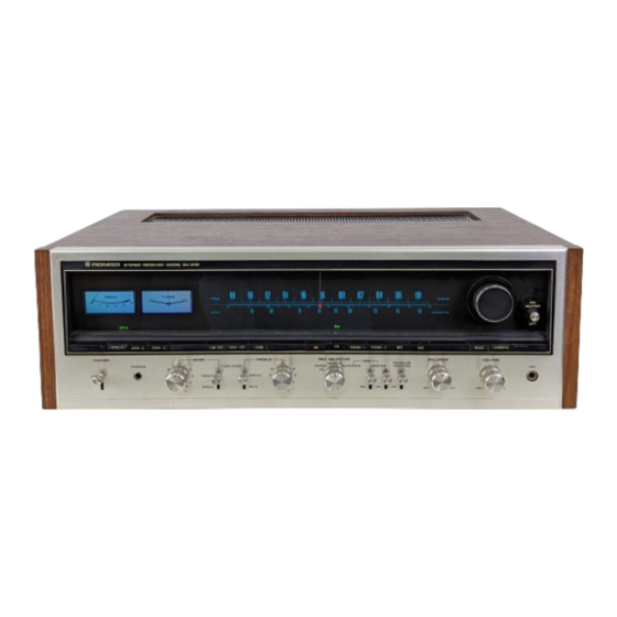
I pulled out my problem child SA-9100 a few days ago to give her a listen for a bit. I got two good days out of her, no protection pops.

Ran it for about 2 hours today when protection popped along with loud buzz from the L channel. Just the one pop this time around. Powerred down and removed speakers

Threw my multimeter on the terminals pretty quick to check for DC. Rmoved all inputs, volume to zero, tone defeat engaged
  • R Channel - Pretty stable reading between 1 and -1 mv
    • Cycle power - quick swing to 40 mv then drops off to normal range
  • L Channel - A lot more variation. DC swing from 0 to about 6.5 mv - occcasional spike as high as 180mv
    • Cycle power - swings higher to about 6omv then drops off
Voltages at power suuply A
  • 1: 46
  • 3: -46
  • 6: -62
  • 7: 62
At Board B: actual vs. (spec)
  • 2: -15.7 (-16)
  • 3: -24 (-24)
  • 4: -13.4 (-13)
  • 5: -40 (-42)
  • 8: 45.5 (42)
  • 9 : 38 (35)
  • 10: 26.5 (24)
  • 11: 17.3 (16)

FIlter caps replaced ~5 years ago some service since then but not sure what has been replaced or not.

I think I'm about ready to just do this myself and stop letting shops chase white rabbits on my dime. So, I could use some sanity check. Here's where I'm at:

  • I'm pretty sure at this point the problem is in the left channel based off the swing in DC at the terminals
  • Protection circuit kind of worked as it shoud but still allowed buzz to L channel when tripped.

Next steps:
  • tomorrow check secondary power supplies for ripple
  • check transisters on protection circuit
  • Verify alignment
  • tentatively plan on replacing Q6 and Q7 on both power amp boards (known problems w them) w/ 512-KSC2690AYS


Anything else? Anything I'm missing?
 
Register to hide this ad
Spiking left channel dc is not a good thing. I hazard the protection circuit may have been doing what it is supposed to.

"Protection circuit kind of worked as it shoud but still allowed buzz to L channel when tripped." Please explain a bit more about buzz when tripped?

Yes on replacing the 2SC1451's in the amp boards. (a very likely cause of the problem)

There are a few other trouble maker transistors in the amp. Might want to replace them?

There are four 2SC1312's in the control amp.

And maybe four 2SC1313's in the EQ board. They may be 2SC1345's and those are usually OK.

Protection circuit tripped, music shut off as it should but immediately followed by loud buzz from the left channel only. Think: touching the open end of a guitar cable or RCA when hooked up to the amp. Loud enough, I was concerned for my speakers (They are OK, thankfully)

At this point, it's been worked on piecemeal by a couple different shops, none of which have been able to eliminate the protection issue (though this is the first time I got the buzz post-trip). I'm ok with doing the work myself but I'd rather take a "while the hood's up" approach and tackle any known issues while I'm at it.

for the 12's and 13's - thinking I should replace with a substitute? KSC1845FTA, maybe?

Appreciate the input!
The description of the buzz is a little alarming. It sounds like the relay did not disconnect the left speaker. Where did you measure the offset?

Yes the KSC1845 would be a good sub.
 
The description of the buzz is a little alarming. It sounds like the relay did not disconnect the left speaker. Where did you measure the offset?

Yes the KSC1845 would be a good sub.
That was my thinking. The protection circuit has been messed with so much, I'm thinking of redoing it along with the relay just to have a clean slate.

Offset measures at the terminals over the course of an hour or so
 
That was my thinking. The protection circuit has been messed with so much, I'm thinking of redoing it along with the relay just to have a clean slate.

Offset measures at the terminals over the course of an hour or so
Which terminals? Speaker or protection or amps?

Any pictures of the top and bottom of the offset board might help somebody spot something.

Many threads about the offset boards. Pioneer used pretty much the same circuit over a wide range of products.
Pretty easy to just replace most of the transistors and the few caps.
 
Sorry. Speaker terminals on the amp.

I'll snap some pics and post them when I get home. Appreciate it
 
Should have done it last night but too focused on testing...

Gonna decouple the pre and power stages tonight to see if I can isolate out. Problem persists: look at power stage. Problem dissipates: focus on pre/control stage.
 
You can make a quick check for a welded relay or some hack job repair.

POWER OFF, UNPLUGGED.

Ohm check from pin one on the protection board to the left speaker output (make sure the speaker switch is set to that output)
Same thing for the right channel. Pin 3 on the protection board to the right speaker output.

Both should be open.

FYI you can monitor the DC offset on those protection board terminals, they are before the relay. If it goes into protection you can still see the DC offset voltage there.

Awesome. I'll add that to my to-do list for tonight.
 
Didn't get as much time to work on it tonight as I'd like but, here's what I got so far:

Primary and Secondary voltages stable with very little ripple

Speaker relay not fused, tested OL on both sides

but.. checking transistors Q1 and Q2 on protection circuit I noticed this:

Base of Q2 got a reading of .03 vac constant
Base of Q1 wild swings from .1 to 2.55vac - Q1 is the one which feeds the left channel.

Now here's where I'd like someone to keep me honest. It looks like a transistor is installed wrong. See the one with the blue dot. If I'm reading the schematic right the base should not be feeding into diode D5. Please tell me if I'm missing something here.

20250127_184158.jpg

Screenshot 2025-01-27 185615.jpg
 
That appears to be Q2? What transistor is installed there? BTW It looks like you have a C rev board I can't clearly see the rest of the number.
It does match the A rev layout you have. Not sure about the schematic.

Your actual board has two diodes just below and between 6 & 7. And at the bottom you don't have three diodes right next to each other just below Q1.

See if you can find a C rev board layout and schematic.
 
Got to take a peek at protection board Q1 and Q2 this morning. Spec had them orignally as 2SC869.

But I got two different transistors in there:
2N555B33
C1815GR331

So I'm thinking replace those with KSC1845FTA along with Q3 and Q4 on the power amp board

Q6 and Q7 on the power amp replace with KSC2752OSTU

To the extent I find any 2SC1312 or 2SC1313, replace with KSC1845FTA

Caps on the protection board are odd though/ I found this little guy along back:

20250127_184819.jpg

this is tied in to the same cap on top of the board at C5 which should be 4.7uF. So thinking of taking those 2 out and replacing with a proper spec cap. (I do wonder if this was part of the reason the relay didn't kick in timely. C5 feeds the relay close at power off and if I'm thinking about this right the increased capacitance could lead to the whump I get at power down.)

Also C3 and C4 should be 330uF but have been replaced by 470uF (I believe this was done to decrease the triggering of the circuit)

C6 appears to be correct.

So, yeah. Good times.
 
Got to take a peek at protection board Q1 and Q2 this morning. Spec had them orignally as 2SC869.

But I got two different transistors in there:
2N555B33
C1815GR331

So I'm thinking replace those with KSC1845FTA along with Q3 and Q4 on the power amp board

Q6 and Q7 on the power amp replace with KSC2752OSTU

To the extent I find any 2SC1312 or 2SC1313, replace with KSC1845FTA

Caps on the protection board are odd though/ I found this little guy along back:

View attachment 3412252

this is tied in to the same cap on top of the board at C5 which should be 4.7uF. So thinking of taking those 2 out and replacing with a proper spec cap. (I do wonder if this was part of the reason the relay didn't kick in timely. C5 feeds the relay close at power off and if I'm thinking about this right the increased capacitance could lead to the whump I get at power down.)

Also C3 and C4 should be 330uF but have been replaced by 470uF (I believe this was done to decrease the triggering of the circuit)

C6 appears to be correct.

So, yeah. Good times.
Somebody did you no favors, dip my hand in the parts bin and slap in whatever comes out. Shameful.

C5 is part of the circuit that quickly opens the relay on power off. Yes put the 4.7uF back.

I would stick with the original value 330uF caps.

Q1 and Q2 are a diff amp and should at least have the same transistor in both places. Hey at least they are both NPN :p

Does it look like any resistors have been messed with?

Looks like a solid plan.

Again, I deeply appreciate the feedback. I'm honestly not surprised it's wonky. The first guy to tackle it turned out to be a real yokel. I wouldn't be the least bit surprised if it was him.

R15 and R16 look like they were replaced but the new ones are in scope at 82Ω so I don't plan to mess with them. As a final blow, when I took a look this morning, one of the wrapped wires at pin 12 snapped off... lol. 7.5v - looks like it feeds the protection light. That will get soldered back on when I'm done.
 
Protection circuit is complete. Two new 1845s in q1 and q2. Got some good intel checking my work out. At the base of q2 I was reading about 4 my at the base of q1 I got 18. And while I had the meter on it, I was able to observe it spiking up well over 100mv, enough to trip the circuit. Left channel which related to what I heard initially.

Unfortunately, mouser shorted me so I have to wait for the rest of my 1845s to come in. Which begs a question: how the hell do you get the power amp board out???
 
Hopefully, my last post on the subject of this amp...

Finally got around to finishing the work last night. Sure enough, there were four 2SC1451's in the power amp sections still. Inexplicably, someone had gone in and replaced the rest of the transistors on the board but not those ones. I can't even... It was a bit of a trick getting the KSC2752OSTU's shoehorned in there but I got it done. Set up the multimeters and spent an hour watching the voltage on the amp inputs and at the base of Q1 and Q2 on the protection board with no meaningful fluctuation. Adjusted the idle and offset on the power boards. One of the VAR's is highly tempermental (which could well have been part of the issues) but got them dialed on spec.

Measured pretty much 0mV DC at the speaker terminals. Threw it on the crappy bench speakers and it sounds amazing even through those things. Ran it for another 2 hours with no issues at all. This weekend, gonna put it on the scope and do one last pass on it but, hopefully this is it for now (gonna swap out the VAR's on the power board eventually).

Also cleaned the faceplate and knobs.

Thanks again, for the guidance!

20250204_193102.jpg
 
Back
Top Bottom