Sansui 9090 Power Supply board rebuild questions

nortoncycler

New Member
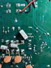
Hi All, first time poster here in the Sansui forum so hoping I could get some advice / help. I've taken on the challenge of rebuilding a really sad, neglected and abandoned 9090 (non DB) Normally I would troubleshoot and fix prior to a rebuild attempt, but given this poor guy's shape and functional status of "not even close" I figured I would just go through and rebuild everything. Anyway I bought a great kit from "that site" and set about my journey. I got as far as Part 1 - Rebuild the power supply and have already hit a issue / question... during my replacing of the caps, I came across it having a bit different configuration (revision?) than apparently most. Instead of the usual 4.7uf caps mine has 4x 10.0uf ceramics and two additional 2.2uf 100v caps... I've seen a few pictures out there of similar boards, so I'm pretty sure this isn't some ad-hoc mod, but was curious what the rebuild advice would be... Leave the arrangement of the 4x 0.01uf's and swap the 2x 2.2uf's with newer ones. Or swap out the 0.01uf's with the 4.7uf's and do ??? with the 2.2uf's??
9090 PS Pic.jpg


All advice, help comments would be GREATLY appreciated!
 
Last edited:
Register to hide this ad
Leave the ceramic disc [.01 uF]. The .01uF are OEM and very reliable/indestructible and replace all electrolytic caps. The rule is to keep the unit as you find it unless it is not OEM. There are a couple of variations of the power supply board so stick with the “original” configuration. There is one notable variation that has a trace cut and a cemet resistor patched in over the cut trace. I am not sure when this was done but if your board does not have this I would leave be.
 

Attachments

  • IMG_1510.JPG
    IMG_1510.JPG
    124.7 KB · Views: 11
  • F2546.pdf
    F2546.pdf
    195 KB · Views: 8
Leave the ceramic disc [.01 uF]. The .01uF are OEM and very reliable/indestructible and replace all electrolytic caps. The rule is to keep the unit as you find it unless it is not OEM. There are a couple of variations of the power supply board so stick with the “original” configuration. There is one notable variation that has a trace cut and a cemet resistor patched in over the cut trace. I am not sure when this was done but if your board does not have this I would leave be.
Thank you so much for the advice and great information!
I'll do exactly as you recommend and just update the 2.2uf's (and other electrolytics) in place and leave the config as-is.... Thanks!!!
 
Leave the ceramic disc [.01 uF]. The .01uF are OEM and very reliable/indestructible and replace all electrolytic caps. The rule is to keep the unit as you find it unless it is not OEM. There are a couple of variations of the power supply board so stick with the “original” configuration. There is one notable variation that has a trace cut and a cemet resistor patched in over the cut trace. I am not sure when this was done but if your board does not have this I would leave be.
Does anyone know WHERE the +29 VDC for the TONE circuit is sourced from ? Sansui didnt document that well at all. Thx
 
Does anyone know WHERE the +29 VDC for the TONE circuit is sourced from ? Sansui didnt document that well at all. Thx
It originates from the F-2546 PSU PCB, where it is pin 15, 36V, I think it then goes to the F-2541 board, then F-2543, pin 13 & F-2544, 33V, pin 05 (Tone Control Board) where it is 'dropped' (by resistors on F-2543) to 28V, pin 12, for use by other boards. You're right, the schematics for these are a shambles - very difficult to read.
 
It originates from the F-2546 PSU PCB, where it is pin 15, 36V, I think it then goes to the F-2541 board, then F-2543, pin 13 & F-2544, 33V, pin 05 (Tone Control Board) where it is 'dropped' (by resistors on F-2543) to 28V, pin 12, for use by other boards. You're right, the schematics for these are a shambles - very difficult to read.
Thanks for that. It's a convoluted way of getting DC to the Tone board for sure. I may do some mark ups and list them here once I fix the issue.
 
I am not sure if I am 100% correct, I got that info just by reading the block diagram of boards and their connections, & following the voltages. (page 18 of the SM).
I too got the DC supply run trail from those documents . But, from my 40+ years in working on all sorts of systems , the 9090 service manual does NOT rank high on the list. There are even circuit board layouts MISSING in the SM
 
It originates from the F-2546 PSU PCB, where it is pin 15, 36V, I think it then goes to the F-2541 board, then F-2543, pin 13 & F-2544, 33V, pin 05 (Tone Control Board) where it is 'dropped' (by resistors on F-2543) to 28V, pin 12, for use by other boards. You're right, the schematics for these are a shambles - very difficult to read.
20260207_174726.jpg
 
THAT toasted resistor on the MIC pre-amp board is the culprit. Now, WHY did it flame out? Are the SIP ICs on the TONE PCB ok and not drawing ridiculous current? I think someone has made a replacement IC for those
Someone may have plugged a powered mic in.
 
Yes, beware of the schematics! They scare the crap out of me. Try to orient everything as it was by taking lots of pics. Otherwise, the silk screening on the boards might screw you, too.
 
Hey guys that image is of a F-2617 Mic PCB from a 9090DB. On a 9090 the Mic Jacks & potentiometer are wired directly to F-2543 "Tone Control Board" per Sansui but it is really the volume/balance control board. See Pix:
 

Attachments

  • IMG_1931 copy.JPG
    IMG_1931 copy.JPG
    185.6 KB · Views: 9
Back
Top Bottom