• The move to the new server is done. There are some software and database maintenance updates in process. This has us passing the hat around to help out. We appreciate any donations. Seriously, even a dollar helps. The payment page may be found here - https://www.audiokarma.org/support.html

Sold 7027A as EL34 equivalent. Amp not working now

Right, all you need to do is put in a switch that disconnects pin 1 from pin 8. I made an amp with a switch which allowed the amp to use el34 by making the connection via the switch. Then when you switched out you could use the 7027, 6550, 6l6gc, etc.

Gotta be careful with that though! I guess if you built the amp yourself you know it's OK. But on 6L6 amps, I often also use pin 1 as a tie point (connecting pin 8 to pin 1 with a current sensing resistor... pin 8 also gets a test point jack and pin 1 gets tied to ground).
 
Very sad the radio guy wrote El-34 on those boxes hope you can fix it up. On a relate mislabeled tube topic 2A3 marked as 45, I have had those wish I had some now to post pictures. 2A3 draw twice the current than 45,s to light filament, A radio friend found one of those 2A3 and placed it in a single ended radio that used 45,s it fried the PT opened the filament connection. Today 2A3,s worth more then 45,s in the past 1950,s into the 60,s 45,s worth more then 2A3,s is why you find these
 
Most likely simple screen resistor, but that should have made a sharp snap sound that you would have heard, could you have mistaken it coming from the unit vs speaker?
 
Most likely simple screen resistor, but that should have made a sharp snap sound that you would have heard, could you have mistaken it coming from the unit vs speaker?
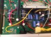
I could have mistaken it because it was instantaneous.
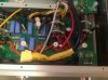
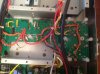
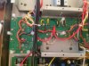
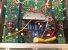
Would it be be obvious from these photos. Thanks for any advice jm
image.jpeg image.jpeg image.jpeg image.jpeg image.jpeg
 
Could be something on the other side of those boards. It shows resistor values but looks like those components are on the other side. For example, what appears to be 10 ohm resistors connected to pin 1 and 8 of each power tube, but mounted on the other side of the board.
 
Last edited:
Yes, you'll probably see a burned out resistor on the other side. The problems with PCBs that they have two sides and the connections are less obvious than point to point.
 
Back
Top Bottom