• The move to the new server is done. There are some software and database maintenance updates in process. This has us passing the hat around to help out. We appreciate any donations. Seriously, even a dollar helps. The payment page may be found here - https://www.audiokarma.org/support.html

Testing new crossover for Altec Valencia/ model 19 clone

powerdoc

Active Member
I just finished construction on a Model 19 Altec crossover clone for use with my Altec Valencia/Heath as-101 speakers. I want to test the crossover before hooking up the speakers to make sure I'm not going to blow the horns. My AF generator puts out 7v RMS. Is this enough to connect to the input and get an accurate output for either my vtvm or scope?
 
Register to hide this ad
I just finished construction on a Model 19 Altec crossover clone for use with my Altec Valencia/Heath as-101 speakers. I want to test the crossover before hooking up the speakers to make sure I'm not going to blow the horns. My AF generator puts out 7v RMS. Is this enough to connect to the input and get an accurate output for either my vtvm or scope?

I'd keep it under 1 volt!! I'd just attach them to an amp or receiver and just run them at a low volume, that won't hurt the horns at all, pictures, we need pictures!! Dave. :music:
 
Hook up a cone driver in lieu of the compression driver as first test. If all you hear is VHF, it's probably O.K.

With Wojo, only 1 volt max required.... :thmbsp:
 
Actually I was going to put the output of the generator directly to the x/over rather than an amp. 7v into a preamp input would be kinda' severe! I'll post some pix; not really elegant but seems functional as far as the wiring technique goes.
 
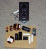
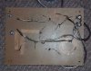
Here are the pics

The "goo" looking stuff around the wires is hot glue to keep the wires from rattling. Each part is also hot glued to keep it stable. The perf board is from RadioShack and I think is 6x8 in. The rest of the components came from Parts Express. Inductors are 18ga, Dayton caps, and 10w non-inductive resistors. The fun part was placing the components so I could just use the wires from each and have to run a minimum of jumpers. I still have to test it then I have attach it to the speakers and cut the appropriate holes for the controls. I have some metal isolation posts that will be screwed into the speaker to support the circuit board. The terminal block is for speaker connection. The red/black binding posts are for connection to the amp from another binding post pair on the back of the speaker. I think that the 100w L-pad (and probably the 50 that's controlling the tweeter) are overkill since the rest of the resistors are 10w. It's wired with 18ga wire. Frankly, I'm not a believer in using high-tech wires for things like this but I did check resistances for cold joints. I turned the inductors in various directions so they would hopefully not interact with each other.
 

Attachments

  • cross1.jpg
    cross1.jpg
    111.3 KB · Views: 83
  • cross2.jpg
    cross2.jpg
    89.2 KB · Views: 52
Looks good. :thmbsp:

I don't know what the DCRs are on the original inductors (I have that somewhere,) but it seems 18 Ga on the 2.7 mH and 0.3 mH could add up to over 1 Ohm in series with the woofer.

Intuitively, I'd use 15 Ga for the 2.7, or even Super-Q, for tighter bass. You may want to try that and see if it makes a difference. :yes:

The 0.3 mH is less of an issue, since the typical setting of the HF rheostat in parallel virtually shorts it out anyway....
 
Z: When you do your curves, are you just manually plotting these as freq vs. output voltage or is there a gizmo you use that plots the curves for you?
 
Z: When you do your curves, are you just manually plotting these as freq vs. output voltage or is there a gizmo you use that plots the curves for you?
A gizmo.

The curves I usually post are actual acoustic output; it listens with a pressure microphone and does the plots, via various test methods.

In crossover development, it also can measure the voltage drives directly vs. frequency. That you can certainly do manually with what you already have. :yes:
 
I think I'm going to plot freq at a certain constant voltage against output to see if I can get a slope and where it is. Lord knows I can take my time as with most of us I've accumulated extra speakers.
 
Back
Top Bottom