• The move to the new server is done. There are some software and database maintenance updates in process. This has us passing the hat around to help out. We appreciate any donations. Seriously, even a dollar helps. The payment page may be found here - https://www.audiokarma.org/support.html

trying to build my first headphone amplifier.

aidynphoenix

Super Member
i have been trying to understand the Mini-CMoy Pocket Amp design and use the parts i have on hand to build my own..
i have the right caps and resistors..

but im having a difficult time understanding how the layout of the op-amp works..

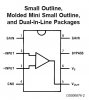
i have two working LM386 amp chips.. each is a 8 pin.

http://www.national.com/ds/LM/LM386.pdf

in the pocket amp that i am trying to basically reverse engineer.
http://www.tangentsoft.net/audio/cmoy-tutorial/misc/mini-cmoy-layout-0150.pdf

it is useing a dual channel opamp.
and i will be trying to use two 1channel opamps..

but i dont understand where the +9v and -9v inputs are on the opamps that i have..

i know where the audio signal inputs are. and where the Vout is..

i understand that 2 and 3 are where my audio signal inputs eventually go..
and that 5. is to the heaphone positive for either channel.
but i dont know where my power inputs go.. and also if the extra pins are unused or not...
 

Attachments
  • opamp design.jpg
    opamp design.jpg
    39.6 KB · Views: 25
Last edited:
Register to hide this ad
bump..


my main question is..
if the Vs (pin6)
is the postitive voltage input?

and if the GND (pin4) is the negative input?

and i am assuming that the resistance between pin (1 and 8) controlls the gain of the amp?
 
Last edited:
if the Vs (pin6) is the postitive voltage input?

and if the GND (pin4) is the negative input?

and i am assuming that the resistance between pin (1 and 8) controlls the gain of the amp?

Correct, but the gain control configuration is peculiar to this model. The gain with pins 1 and 8 left open (20x) is probably a bit more than you need, and it cannot be reduced -- only increased.
 
Yeah, 20X is quite high. When I built my C-moy (3 or so years ago) It started off with 10X gain and I found THAT to be too sensitive for my taste! I eventually settled out at a 4X gain.

Typically the higher the gain, the more susceptible the circuit will be to RF/EM noise as well.


`
 
ok so i will either have a very sensitive amp..
or need a higher pot value?

You could add a series resistor on the high side of the pot (CW end) of perhaps three times the pot value, to attenuate the input signal. Modify the value after testing, if you want more or less overall gain.
 
well i used a different chip..
this one is dualchannel so it made this a bit easyier.
6458D-3u9
i had a hard time finding a product sheet on it. i found it under LA6458D.
i didnt have all the right type resistors so i had to use several ones in some places.
i also did without the potentimeter for now because i am testing it with my ipod and it has its own volume controll.

i also left out the resistor led and diode.. figured that was simply for the led.

as far as sound quality. i cant give a opinion untill i try it on a line out on a dvd player or something else line out.. but it sounds just fine on my ipod's headphone out.


but i have a question..
in the pocket amp it has two 9v batterys in series.. i am testing it with a single 9v..

so this means that it is supposed to have 18volts power right?

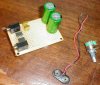
pics to come very soon

BTW: merry christmas everybody!
 
Hi
The cmoy uses a dual rail psu so the two 9volt batterys will give you 9-0-9 volt.
The + contact from one battery goes to + on the opamp the - contact of the other battery goes to the - on the opamp. now connect the remaing + and - of the two batterys together this will be at ov reffrence and is usualy called power ground this is where the ground return of your headphones will conect to. using a dual rail supply means no capacitor is needed to block dc from the output . also you will find you do not need anywhere as much gain as with just one 9v battery. PS the + and - im am talking about is the opamp power connections not the +non inverting and - inverting inputs

Seasons greetings to all Karmarites
 
Last edited:
well i used a different chip..
this one is dualchannel so it made this a bit easyier.
6458D-3u9

i also did without the potentimeter for now because i am testing it with my ipod and it has its own volume controll.

i also left out the resistor led and diode.. figured that was simply for the led.

as far as sound quality. i cant give a opinion untill i try it on a line out on a dvd player or something else line out.. but it sounds just fine on my ipod's headphone out.


but i have a question..
in the pocket amp it has two 9v batterys in series.. i am testing it with a single 9v..

so this means that it is supposed to have 18volts power right?

pics to come very soon

BTW: merry christmas everybody!

Yeah, I built mine specifically for use with my Ipod, so I never added a vol pot... Also okay to omit the LED components (res/diode)


As far as 9v vs 18v, I don't know the Vmin for your op-amp(s). The C-Moy I built, incorporates the OPA132/134 family op-amp... Personally, I use (2) 9v batteries but it also works fine with ONE 9v supply!

I'm not sure why you chose the C-Moy if you didn't plan on using op-amps which complement the C-Moy's configuration. It can't be the cost.... They only run a couple $$$'s.

There are many Op-amps which aren't even suited for audio.... Not sure If yours is or isn't!.

"Other" Op-Amps require different configurations (circuitry) to perform well. Usually, the "overall" amplifier design/configuration is built AROUND the chip being used, not the other-way-round!


`
 
Back
Top Bottom