• The move to the new server is done. There are some software and database maintenance updates in process. This has us passing the hat around to help out. We appreciate any donations. Seriously, even a dollar helps. The payment page may be found here - https://www.audiokarma.org/support.html

Onkyo M-5030 stuck in protection

plyzo

Super Member
Hello AK guys,

Could use some help with an Onkyo I have on the bench that is stuck in protection. Under DBT I went ahead and just remove the outputs to see if maybe unit might come out of protection. This unit has 3 relays and I assume there is one each for L & R. I did check for DC at each of the relay legs and found no DC.

The only place I found DC was the middle relay at Pins 13 & 14.

D122 Diode had 13v on anode and cathode side.

Not sure if I am going down the right direction by checking these areas.

Anyone worked on these units before that might steer me in the right direction?

Appreciate it.


M-5030.png
 
Register to hide this ad
Q102 - Relay Driver reads
E: 14
C: 0
B: 13.3

Collector on Schematic says it should have 14v.
Pulled and tested and was good.
 
Connected back the output transistors and checked idle current even though I have no relay click and only getting 5mv instead of the required 14mv. Not able to adjust it with the trimmer resistors, so something is going on with the idle current.

Output Measurements:

2SA1106
E: 53v
C: -53v
B: 53v - Should be -0.6

2SC2581
E: 52v
C: 55v
B: 53v - Should be 0.6
 
Wanted to report back on progress. I was able to narrow it down to a few diodes that were bad and now able to get unit to idle current working properly. The relay still won't click correctly unless I remove the left side cable and let the relay click then plug the cable back in. I checked DC at the relay pins and there is none so thinking maybe the relay isn't working correctly.
 
I don't get it. You have 0.6 V across B-E from Q102. This means it should be on. Yet it isn't but when you test it your tester reports it is OK. Wozzup with that? I also don't get your output measurements. These values show that your output is railing (at the positive rail). That means Q102 should never be on in the first place. Look up the datasheet of the TA7317. Pin#2 and 3 should be at zero but this way that never can be the case. It is in protect as it should be.

I'd suggest to first find out why your outputs rail. If need be remove the output transistors and do the lazy engineer's method (look it up). You will prolly find that when you fix the drive of the outputs (lazy method) your amp comes out of protect. But something is not right here...
 
I don't get it. You have 0.6 V across B-E from Q102. This means it should be on. Yet it isn't but when you test it your tester reports it is OK. Wozzup with that? I also don't get your output measurements. These values show that your output is railing (at the positive rail). That means Q102 should never be on in the first place. Look up the datasheet of the TA7317. Pin#2 and 3 should be at zero but this way that never can be the case. It is in protect as it should be.

I'd suggest to first find out why your outputs rail. If need be remove the output transistors and do the lazy engineer's method (look it up). You will prolly find that when you fix the drive of the outputs (lazy method) your amp comes out of protect. But something is not right here...
Q102 has the following reading:

B: 12v
C: 0v
E: 12v

What I don't get is when I remove FC102 (which is the left side connection), the relay then clicks on and is good.
Q102 then reads:

B: 13v
C 14v
E 14v
 
Pulled Q102 and tested again.
Getting the following:

HFE:213
UBE:575mv
Ic:2.0mA

Checked voltages of BCE on the board with transistor removed.

B:12v
C:0v
E:12v
 
I am suspecting it might be TA7317P because at Pins 2,3 I have 0v which would be no DC.

Current values with unit on no relay click:
1. -0.7v
2. 0v
3. 0v
4. 0v
5. -0.7v
6. 11.2v
7. 1v
8. 0v
9. 3v


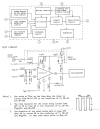
TA7317.png
 
Replaced Q101 TA7317P and now the relay does click but with no delay.
Values seem all over the place too:

Q101
1. 2.3v
2. 0.8v
3. 0v
4. 0v
5. 1.1v
6. 4.2v
7. 3v
8. 3v
9. 10v
 
Purchased the TA7317P from eBay and I suspect it's a counterfeit and no good.
I was lucky enough to get a working unit to compare.

The working version with relay click has the following:
Q101
1. -0.7v
2. 0v
3. 0v
4. 0v
5. -0.7v
6. 1.4v
7. 0v
8. 1.2v
9. 3.2v

The unit with no relay click:
Q101
1. -0.7v
2. 0v
3. 0v
4. 0v
5. -0.7v
6. 15.5v
7. 2.3v
8. 0v

9. 3.2v


On the working unit Pin 6 starts with 13v then when relay clicks it goes to 1.4v.
This one really has me stumped.

ta7317.png
 
@PE9ZZ Have any thoughts on where to go from here?
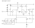
No. The TA7317 is a bit of a crap chip. But it is also a simple circuit:

TA7317P_internals.png


If you have more than 0.7 V on pin #7 it is borked. Dunno what D120 is supposed to do. Short it to GND and see if it will switch on.

Pin #8 is the powerup delay. The datasheet does not say what the threshold is for it to switch on but it looks like 2 V or so. It is zero because of pn #7.
 
No. The TA7317 is a bit of a crap chip. But it is also a simple circuit:

View attachment 3507810


If you have more than 0.7 V on pin #7 it is borked. Dunno what D120 is supposed to do. Short it to GND and see if it will switch on.

Pin #8 is the powerup delay. The datasheet does not say what the threshold is for it to switch on but it looks like 2 V or so. It is zero because of pn #7.
Shorting Pin 7 to GND did nothing. But if I short Pin 6 to GND then the relay will click.
This chip came out of a working unit so I suspect it has to be something else going on within the protection circuit but I've checked diodes and resistors and all seem to test fine. I must be missing something.
 
Last edited:
But if I short Pin 6 to GND then the relay will click.
Of course it will click. That is what pin #6 should do. But if pin #7 is not zero and if shorting it to GND does not result in >CLICK< your chip is bad. See the internals above. Also note that pin #8 should NOT be zero. This is what should cause pin #6 to energize your relay in the first place.

Get a new one.
 
Last edited:
Of course it will click. That is what pin #6 should do. But if pin #7 is not zero and if shorting it to GND does not result in >CLICK< your chip is bad. See the internals above. Also note that pin #8 should NOT be zero. This is what should cause pin #6 to energize your relay in the first place.

Get a new one.
Alright the search begins for a non counterfeit. Appreciate your help. Interesting part is that if I take this chip out and put it in the other unit, it works just fine and comes out of protection.
 
Then you're overlooking something. I say: pin #7.
Alright new TA7317 and still no luck coming out of protection.
But if I ground and hold pin 7 for about 3 seconds the relay clicks.

Here are the values before relay click:

P1: -0.7v
P2: 0v
P3: 0v
P4: 0v
P5: -0.7v
P6: 10v
P7: 1.5v
P8: 0v
P9: 2.9v
 
But if I ground and hold pin 7 for about 3 seconds the relay clicks.
That's a new development. This means that the chip works as intended. You will see the voltage on pin #8 rise until the relay engages. Now your question becomes: why is pin #7 not zero? Leaky D121? C113? Goo on PCB? What happens if you isolate pin #7?
 
Back
Top Bottom