• The move to the new server is done. There are some software and database maintenance updates in process. This has us passing the hat around to help out. We appreciate any donations. Seriously, even a dollar helps. The payment page may be found here - https://www.audiokarma.org/support.html

Troubleshooting another Magnavox 9300 console pull amp

BmWr75

Top octave? pfffffftttttt
Subscriber
Update: Found an Analog Discovery 2 measurement error after posting the first test results here a while back. The external 5V PSU has to be used to get accurate measurements on this amp. Updated results are in Post 9.

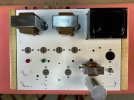
This amp was built probably back in the 1990s by the South Florida Audio Society. The Analog Discovery 2 measurements can be found here (now know these results were erroneous).

The amp hits 2% THD at about 2.4 watts and 5% at about 3 watts using 8 ohm dummy loads. That seems like poor performance to me for a push/pull EL84 amp. There is a good chance the OPTs are rated for 4 ohm loads.

Found what looks to be the right schematic here on AK, but it is pretty hard to read when printed. Anyone have a clearer version suitable for printing?

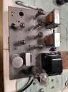
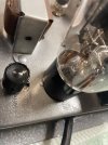
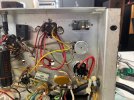
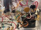
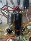
Pics of the amp are attached.
 

Attachments

  • Magnavox_93xx console amp series.jpg
    Magnavox_93xx console amp series.jpg
    108.5 KB · Views: 38
  • IMG_0478.jpeg
    IMG_0478.jpeg
    310.2 KB · Views: 35
  • IMG_0479.jpeg
    IMG_0479.jpeg
    242.2 KB · Views: 27
  • IMG_0480.jpeg
    IMG_0480.jpeg
    227.3 KB · Views: 28
  • IMG_0471.jpeg
    IMG_0471.jpeg
    319.6 KB · Views: 25
  • IMG_0472.jpeg
    IMG_0472.jpeg
    294.9 KB · Views: 24
  • IMG_0473.jpeg
    IMG_0473.jpeg
    280.4 KB · Views: 24
  • IMG_0476.jpeg
    IMG_0476.jpeg
    247.8 KB · Views: 28
  • IMG_0475.jpeg
    IMG_0475.jpeg
    314.5 KB · Views: 24
  • IMG_0474.jpeg
    IMG_0474.jpeg
    318 KB · Views: 29
Last edited:
Register to hide this ad
One more pic.

Measured the plate voltage on all four 6BQ5s: 321VDC, 322, 321, 323

Measured the cathode voltage on all four 6BQ5s: 13.1 VDC, 13.1, 13.1, 13.1

Seems strange to me that the 6EU7 to 6BQ5 coupling caps are: 0.1uF/400V, 0.0068uF/600V, 0.1uF/400V, 0.47uF/400V

The schematic shows all four are not the same values, but seems the .0068 and 0.47 should be the same.
 

Attachments

  • IMG_0477.jpeg
    IMG_0477.jpeg
    267.2 KB · Views: 4
The coupling caps should be the same channel to channel, but all 4 are not the same value. That distortion figure is also excessive.

I'm curious how good those output tubes are, and if you can determine what sort the distortion is. If its even-order that says the signal balance out of the inverter is bad. If there is crossover distortion its a bias problem. If its clipping thats probably a power supply issue. Voltages look reasonable, but if the rectifier is very weak and causing the voltage to drop with a bit of load something is wrong. If there is a lot of 120hz noise or power supply modulation that would point to weak power supply caps.

These are supposed to work into a 4 ohm load too so that may be part of it but I don't recall Dave's initial testing of one of these in stock form to be that bad. They can be made a lot better of course.
 
The coupling caps should be the same channel to channel, but all 4 are not the same value. That distortion figure is also excessive.

I'm curious how good those output tubes are, and if you can determine what sort the distortion is.
The schematic in Post 1 shows 6BQ5 tubes V2 and V5 use a .0015uF coupling cap. 6BQ5 tubes V3 and V6 show a .047uF coupling cap. None of the coupling caps installed in the amp match these values.

I'll test all the tubes in the amp and report back.
 
I'm curious how good those output tubes are
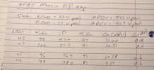
Here are the rectifier and power tube results. My Amplitrex tester requires an adapter to test 6EU7 tubes, which I don’t have. V6 is weak compared to the others. Will move V5 to V3 and look for a better match pair for V5 and V6.

IMG_0481.jpeg
 
hm, that seems reasonable enough. V6 is a little tired but not enough to be a massive problem.

How do the voltages look at the 6eu7 vs schematic?

lots of coupling cap values got bumped to try and get better bass. It usually doesn't work but it shouldn't cause massive mid band distortion. Could cause LF stability issues though.

If the resistors in the voltage divider for the inverter are off it really screws up the balance too. Thats one of the things Dave's re-work addresses. The floating paraphase is far less fussy about specific tube condition and resistor values.

1768242355946.png
 
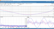
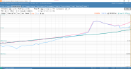
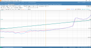
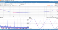
@gadget73 - just had a major Analog Discovery 2 measurement unit learning. This AD2 can be powered off the USB connection. That is how I ran it for most of the test work done so far. Also purchased a 5V power supply and decided to start using it to see if any test results changed. Boy Howdy does the 5V PSU make a difference. Chart 1 below is PSU OFF, second chart is PSU ON (you have to tell the AD2 to turn on the PSU each time the software is booted). THD measures much lower with PSU ON.

Most of the distortion is 2nd order. You can see the 2nd and 3rd order distortion plots in charts 3 and 4 below.
 

Attachments

  • 1c - THD vs Frequency - 3rd order - PSU ON.png
    1c - THD vs Frequency - 3rd order - PSU ON.png
    167 KB · Views: 12
  • 1a - THD vs Frequency - 2nd order - PSU ON.png
    1a - THD vs Frequency - 2nd order - PSU ON.png
    169.5 KB · Views: 12
  • 1 - THD vs Frequency - total - PSU ON.png
    1 - THD vs Frequency - total - PSU ON.png
    167.7 KB · Views: 12
  • 1 - THD vs Frequency - total.png
    1 - THD vs Frequency - total.png
    136.9 KB · Views: 12
Last edited:
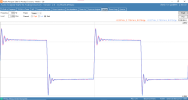
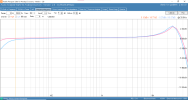
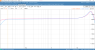
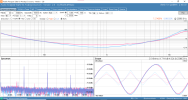
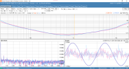
Here are the five standard measurement charts for this amp, all with the 5V PSU powered on. Both 8 ohm and 4 ohm load results shown.

With an 8 ohm load, the amps hits 2% THD at about 9.3 watts. With a 4 ohm load, it hits 2% at about 2.7 watts, but stays near that level of THD all the way to 10 watts.

Much better test results than previously reported when the 5V PSU was not being used on the AD2 test unit.
 

Attachments

  • 5a - Square Wave 4 ohm load.png
    5a - Square Wave 4 ohm load.png
    63 KB · Views: 10
  • 5 - Square wave.png
    5 - Square wave.png
    62.5 KB · Views: 10
  • 4a - Sine Wave 4 ohm load.png
    4a - Sine Wave 4 ohm load.png
    68.5 KB · Views: 9
  • 4 - Sine wave.png
    4 - Sine wave.png
    69.6 KB · Views: 10
  • 3a - Frequency Response 4 ohm load.png
    3a - Frequency Response 4 ohm load.png
    63.2 KB · Views: 9
  • 3 - Frequency Response.png
    3 - Frequency Response.png
    59.1 KB · Views: 14
  • 2a - THD vs Power 4 ohm load.png
    2a - THD vs Power 4 ohm load.png
    89.8 KB · Views: 15
  • 2 - THD vs Power - total.png
    2 - THD vs Power - total.png
    90.5 KB · Views: 14
  • 1b - THD vs Frequency 4 ohm load.png
    1b - THD vs Frequency 4 ohm load.png
    142.2 KB · Views: 14
  • 1 - THD vs Frequency - total - PSU ON.png
    1 - THD vs Frequency - total - PSU ON.png
    167.7 KB · Views: 13
Last edited:
If I remember right, the OPT's have 3.7 ohm secondaries.
They are nice amps once sorted.

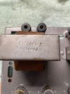
I think that is correct and changing to 8 ohm OPTs makes a big difference per @dcgillespie (if I recall correctly). Although, this amp tests better with an 8 ohm load on the speaker outs from a THD vs Power standpoint. Have attached a picture of the numbers on the OPTs. Maybe somebody will know if these were stock when it was all original.
 

Attachments

  • IMG_0483.jpeg
    IMG_0483.jpeg
    182.3 KB · Views: 6
  • IMG_0482.jpeg
    IMG_0482.jpeg
    185.2 KB · Views: 6
Last edited:
So, this amp doesn't have near the issues I thought it did after the first round of AD2 measurement results were taken a few weeks ago.

Current plan is to install new coupling caps with the correct values per the schematic: V2 and V5 use a .0015uF coupling cap, V3 and V6 show a .047uF coupling cap. Will also find a better matched pair of 6BQ5s for one channel. Will retest after that and decide if anything else needs to be done.
 
Hopefully this helps
Much better. Thank you Mr. Swankey!!

I wonder why V2 and V5 show the coupling cap to be .0047uF and parenthetically (.0015uF), while V3 and V6 show .047uF??
 

Attachments

  • Screenshot 2026-01-12 at 3.49.59 PM.png
    Screenshot 2026-01-12 at 3.49.59 PM.png
    64 KB · Views: 4
Last edited:
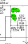
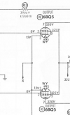
That schematic is so clear .. can anyone explain what the "x" means coming off the cathode of the upper output tube ? And why does there appear to be 2 values for R13 ?
 

Attachments

  • 1768258248373.png
    1768258248373.png
    71.5 KB · Views: 7
I think that is correct and changing to 8 ohm OPTs makes a big difference per @dcgillespie (if I recall correctly). Although, this amp tests better with an 8 ohm load on the speaker outs from a THD vs Power standpoint. Have attached a picture of the numbers on the OPTs. Maybe somebody will know if these were stock when it was all original.

Your numbers are very close to these on a 9302.
 

Attachments

  • IMG_5771.JPG
    IMG_5771.JPG
    111.6 KB · Views: 6
That schematic is so clear .. can anyone explain what the "x" means coming off the cathode of the upper output tube ? And why does there appear to be 2 values for R13 ?
Look at the Power Transformer portion of the schematic. X comes off one of the lower voltage windings.

On R13, am just guessing, but the value in parentheses is probably used if the lower value coupling cap in parentheses is used between the 6EU7 driver tubes and V2 and V5.
 
THX - I see that now -- this would be the heater circuit I am guessing ..
Cathode voltage. You will see that X ties to the cathodes of each 6BQ5 power tube. Heaters are connected to W and Y off the same power transformer winding.
 
Or if you're re-doing it, you can do it per Dave's schematic using the stock iron. Makes a big difference without having to buy transformers. There is still some power loss but even with it, loaded to 8 ohms it does better than in stock config with 4 ohm speakers.
 
Or if you're re-doing it, you can do it per Dave's schematic using the stock iron. Makes a big difference without having to buy transformers. There is still some power loss but even with it, loaded to 8 ohms it does better than in stock config with 4 ohm speakers.

Just read through @dcgillespie 9300 mod thread. Looking forward to investigating each mod further. Right now am wondering if the multi-cap can is original. Will take some pics of it and post them tomorrow.
 
Back
Top Bottom