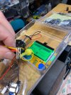
That looks a lot better than mine, so I think it's good.Sure. See attached


That looks a lot better than mine, so I think it's good.Sure. See attached

I measured on the transistor leg not the foil side. This Q1 is a new transistor. I took out the old one when it was pulled and tested good. It is not the Tip41 I inquired but the D313.A thing still bugging me, is the fact this Q1 has a difference of 1.5 Volts between B and E. This is simply not possible if a normal transistor is good (unless it is a darlington transistor or the ACTUAL collector is open circuit).
One thing to note is whether the collector is actually attached, is this 48V measured on the track side or the transistor itself (should be present on the transistor metal tab so easy to reach).
So the question @golfnut is: did you measure the actual 48V somewhere on the trace, or on the collector of the transistor itself (in the end, the metal tab having this voltage is easy to reach)
See picture. It measures .2ohms. Please note that R10 resistor leg is still lifted.The theory is, if considering the 22k and 16k resistors are good the the voltage which should be on the emitter of Q1 can be calculated from the base voltage of Q2 divided by 16 and multiplied by (16+22), so 38/16 times the voltage present on the base of q2. This Q1 emitter output voltage should be there regardless of the load. The voltage on the base of Q1 should be some 0.7 volts higher than its emitter only.
(side note: Another way to check grounding of the circuit card (power off!) is checking the resistance between pin 5 and pin 18 of this power board.
Pin 5 and 18 are NOT connected to each other on the power board itself, but it still should measure as a short through cabling and board ground connetions)
Thanks for this! Much appreciated.(@golfnut do not worry about others get overloaded, just assume not everybody avail at all time or feel like putting time in some remote piece of electronics somewhere on the planet. Every tech started somewhere and most threw things in the garbage which they would have repaired within an hour having present knowledge and measuring tools)
For the time being, I’ll leave this for later. However looking at the transistors, they all have the black legs. I have read where that could be an issue.@golfnut
With R10 lifted, the voltage on pin 14, 15 and 16 look stable and it indicates one more issue on the Equalizer Amplifier Assembly AWF-011.
The AWF-011 has no influence on the protection relay, so it’s up to you if you leave it for later or work on it in the meantime.
(R10 leg still lifted, relay clicks off and on)Tell us which transistors are factory installed.
What you should check are the installed transistors and if you find SA725 and SC1313 change them. Take care with the pinout.
Post a picture from the part side, before you change parts.
I would leave R10 out until the transistors checked and the bad ones replaced.
The same with the caps. At least replace C1, C2, C11, C13,
If it were mine, I would not hesitate and replace all 6 transistors and every single electrolytic on that board as well.
Please take your time, use the lessons learned, take pictures before you change something and test every old part, make notes and test as well every new part before you install it.
Moving on to the protection board AWM-025.
Provide the actual dcv with black to ground for
Pin 1
Also jumps around -.02 to -.11Pin 3
Jumps around mostly except one leg each on D6-7. See pictureD5 anode and cathode
D6 anode and cathode
D7 anode and cathode
Sorry I must have missed the list. Which list are you referring to? I thought I was going by your post.Sorry, but I like to see more voltages. Please use the list for a better overview.
And tell us, what parts you have changed already on the protection board.
Numbers appear to be all over the place on some or most. See attached. Note that no parts have been removed or replaced on this board.Sorry, but I like to see more voltages. Please use the list for a better overview.
And tell us, what parts you have changed already on the protection board.
Pin 18 = 0The jumping around voltages all over has me super suspicious of a bad ground reference still. Just can't think of where to look aside from Pin 18 on the PSU.
With power on, measure DC between PSU pin 18 and chassis. Then between PSU pin 18 and each board ground. Anything more than a few mV or anything that wanders points to a ground problem.
Please see above ground readingsBoard Grounds:
Power Amp - Pin 11 = 0
Control Amp - Pin 4 = .3mv
EQ Amp - Pin 4 = 0
Tuner - Pin 2 = .3mv
Protection - Pin 4 = 0
48VDC on Pin 3? Is that right? That used to be much lower. I'm not even sure how that number is possible.Numbers appear to be all over the place on some or most. See attached. Note that no parts have been removed or replaced on this board.
Those look fine. Such a head scratcher this one is.Pin 18 = 0
Please see above ground readings
Sorry, I used his mv should be and it is -48mv.48VDC on Pin 3? Is that right? That used to be much lower. I'm not even sure how that number is possible.
48VDC on Pin 3? Is that right? That used to be much lower. I'm not even sure how that number is possible.
No worries. The only caps I have replaced on the AWH-033 are the blue caps at C1 and C2. I Used 4.7uf 80vThere are some issues on the protection board with influence on Q6 and Q7
I’m not always convinced from your measured voltage, but if your reading on pin 1 and 3 (AWM-025) is really below 80 MilliVolt for now, there is a good chance that you can get it down with a new DC and offset adjustment.
But before that, please post all the caps you have changed on the power amp AWH-033.
Sorry to ask for it, but I lost track on that.
Was that a typo or what do you mean?Edit: the leg is still lifted on R9 AWR-057
I forgot to mention that the resistor leg was still lifted that’s all.Was that a typo or what do you mean?
Ok. We can come back to that.Dont forget from post #484
The AWF-011 has no influence on the protection relay, so it’s up to you if you leave it for later or work on it in the meantime.
..... I would leave R10 out until the transistors (on the AWF-011) checked and the bad ones replaced.
I’m waiting on these to arrive. I ordered these last week.Wait with the DC offset and bias adjustment for now.
To find the issue on the protection board we could to more testing, or what I would do on mine, I would replace at least
Q1 and Q2, old 2sc869 with KSC1845FTA
I guess I need to order this.Q6, old 2sc945 with KSC2383YTA
Here is the old 2sc1384Q7, old 2sc1384 with KSC2690AYS
Q3, Q4 and Q5 only if they are bad.
C1 and C2 as well, if you have to order them new, go for film caps.
The 2SC1384 relay driver (Q7) is a known culprit for getting old and tired, and dropping the relay randomly. Many will add a flyback diode on the board across the relay coil to protect Q7, cathode to pin 10, anode to pin 9.
Also the overload detectors (Q1 + Q2) will cause random dropping if they get leaky with age.
---------------
If you prefer more testing, follow the procedure in this thread.
Don’t get confused with the SX-828, but it has the same protection board AWM-025 like the SX-737.
easy quick protect board testing procedure
Did Pioneer use two protection boards in the SX-828?
And ONE more Time, to test every old and new transistor before you replace them!
The lead arrangements for the transistors, original or replacement, are all over the place with ecb, ebc, bce and beyond...
Be SURE it's NOT a new Fairchild c945 which is ebc versus an original c945 which is ecb or a new fairchild c945c which is ecb.
You would not believe just how many problems THAT has caused.